Detector Settings and Data Acquisition Problems Affecting LC Sensitivity
Guide to optimizing detector settings and data acquisition parameters in liquid chromatography to prevent sensitivity loss and ensure accurate signal capture.
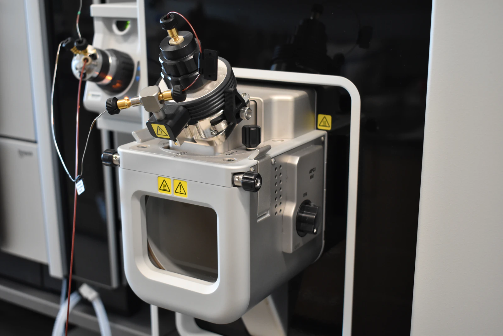
Practical troubleshooting guide for partial or complete loss of detector response in liquid chromatography (LC). This article explains common causes, diagnostic workflows, and corrective actions used to restore reliable detector signal in routine analytical applications.
System Type: Liquid Chromatography (LC / HPLC / UHPLC)
Instrument Component: Detector and Signal Acquisition Path
Symptom: Little or No Detector Signal
Little to no detector response is observed despite normal mobile-phase flow and successful sample injection. The chromatogram may show a flat baseline, extremely low peak intensity, or a complete absence of analyte response.
Common observable indicators include:
Flat or near-zero detector signal
Injection marker present with no corresponding peak
Sudden loss of signal after a method or wavelength change
Gradual decrease in detector response over multiple injections
Root Cause Analysis: Why Detector Response Is Lost
Loss of detector response in liquid chromatography most commonly arises from detector configuration errors, optical path contamination, inappropriate acquisition parameters, or analyte detectability limitations. In many cases, the detector hardware is functional, but operating conditions prevent measurable signal generation.
Typical contributing factors include:
Incorrect wavelength, bandwidth, or response mode selection
Fouling or blockage of the detector flow cell or optical window
Data acquisition rate or time constant mismatched to chromatographic peak width
Signal intensity outside the detector’s effective linear dynamic range
Insufficient analyte absorbance or intrinsic detector response under the selected detection technique
Diagnostic Workflow: Step-by-Step Troubleshooting
Step 1: Verify Detector Configuration
Confirm that the detector wavelength, bandwidth, response mode, and reference wavelength (if applicable) are correctly configured for the target analyte. Incorrect wavelength selection is one of the most common causes of apparent signal loss in UV-based detectors.
Step 2: Inspect the Detector Flow Cell and Optical Path
Examine the detector flow cell for contamination, air bubbles, or physical blockage. Fouled optical windows or partially blocked flow cells can significantly attenuate detector response even when flow rate appears normal.
Step 3: Confirm Data Acquisition Parameters
Ensure the acquisition rate and time constant are appropriate for the chromatographic conditions. Narrow or fast-eluting peaks require sufficiently high sampling rates to prevent peak averaging or signal suppression.
Step 4: Test Detector Response with a Known Standard
Inject a simple, well-characterized compound with a known detector response, such as caffeine for UV detection. This step distinguishes detector performance issues from sample- or method-specific problems.
Step 5: Evaluate Sample Concentration and Detector Linearity
Confirm that the sample concentration falls within the detector’s linear operating range. Samples that are too dilute may fall below the detection limit, while overly concentrated samples may saturate or distort detector response.
Step 6: Assess Detection Technique Suitability
If analyte response remains weak, evaluate whether the selected detection technique is appropriate. Some compounds require alternative detection methods such as fluorescence, refractive index, or mass spectrometric detection.
Corrective Actions to Restore Detector Signal
Reconfigure detector wavelength, response mode, and reference settings
Clean or replace the detector flow cell following manufacturer-recommended procedures
Remove air bubbles and ensure complete flushing of the optical path
Adjust acquisition rate and signal filtering parameters
Modify sample concentration to fall within the detector’s linear response range
Implement an alternative detection technique if intrinsic analyte response is insufficient
Preventive Best Practices for Reliable Detector Performance
Perform routine detector flow cell cleaning as part of scheduled maintenance
Verify detector response during method development and validation
Document and review detector parameter changes
Use system suitability standards to monitor detector performance
Track signal trends over time to identify gradual performance degradation
Related Chromatography Troubleshooting Topics
Low signal-to-noise ratio in liquid chromatography
Detector flow cell contamination or blockage
Reduced quantitative accuracy and precision
Poor method robustness and reproducibility
(Internal links to related troubleshooting articles should be inserted here.)
Frequently Asked Questions About LC Detector Signal Loss
Why does my LC detector show no signal after injection?
This is most commonly caused by incorrect detector configuration, blocked flow cells, or inappropriate wavelength selection. Verifying detector settings and injecting a known standard are the fastest diagnostic steps.
Can incorrect wavelength selection eliminate detector response?
Yes. If the selected wavelength does not match the analyte’s absorbance maximum, detector response may be negligible even though analyte elution occurs normally.
How can I confirm whether my LC detector is functioning properly?
Injecting a well-characterized standard with known detector response is the most reliable way to confirm detector functionality and isolate method-related issues.
Technical Scope and Authority
This troubleshooting guidance reflects standard analytical laboratory practices and commonly accepted service diagnostics used across liquid chromatography systems in research, quality control, and regulated laboratory environments.