Flow Rate Inaccuracy in HPLC and Retention Time Variability
Step-by-step guide to fix Flow Rate Inaccuracy in HPLC and Retention Time Variability: isolation steps and corrective actions to stabilize retention times.
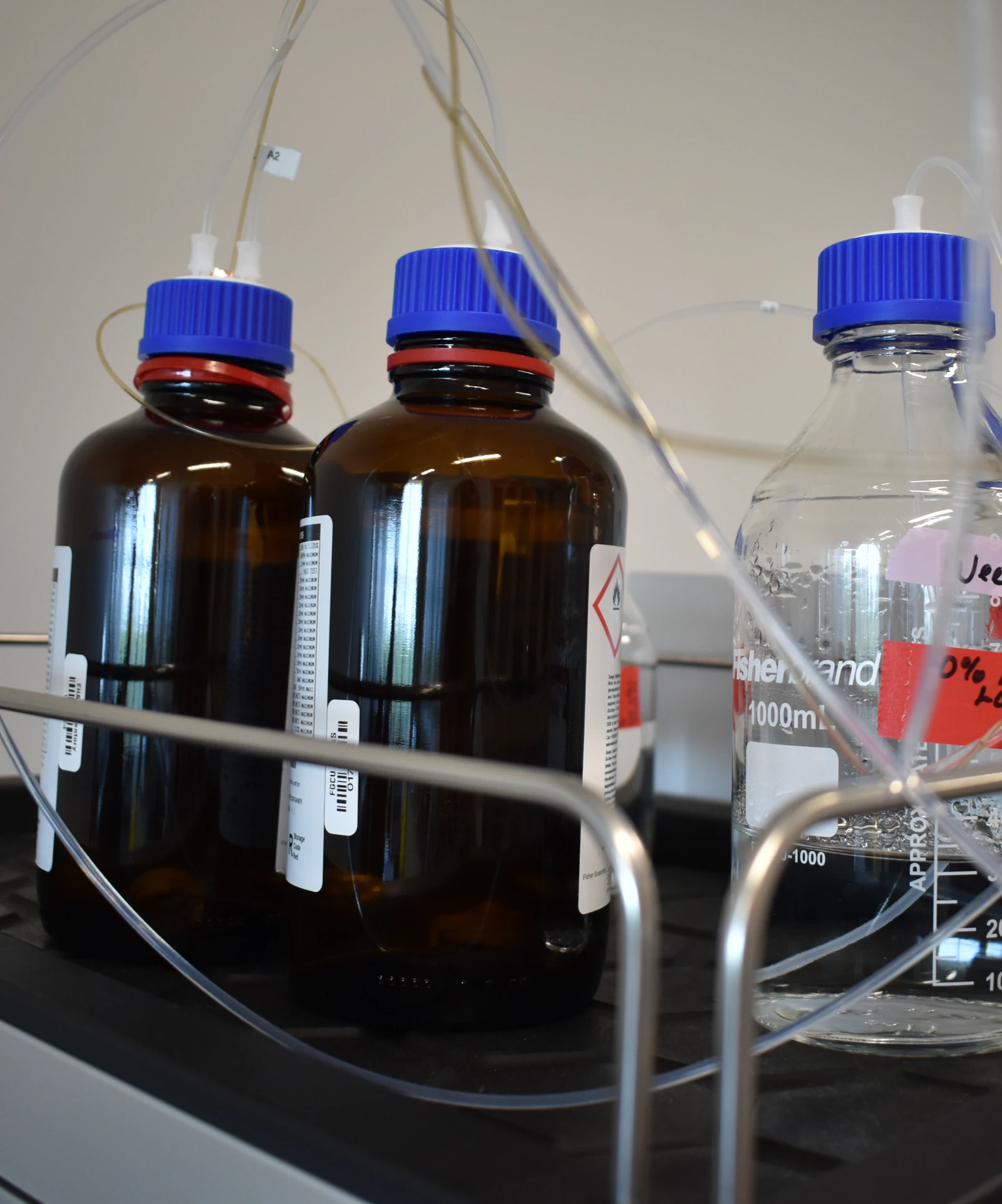
Diagnosing Flow-Rate Inaccuracy and Retention Time Variability in HPLC
Root Causes, Quantitative Relationships, and Corrective Actions
Overview
Accurate and reproducible flow delivery is a foundational requirement in high-performance liquid chromatography (HPLC). Even modest deviations in delivered flow rate can produce measurable retention time shifts, distort gradient profiles, and compromise method robustness. In isocratic separations, retention time is directly coupled to flow; in gradient separations, flow accuracy interacts with solvent proportioning, dwell volume, mixing efficiency, and system delay, amplifying variability.
This guide provides a systematic, quantitative framework for diagnosing flow-rate inaccuracy and retention time variability. It integrates pump mechanics, solvent properties, gradient delivery, column behavior, and autosampler effects into a practical troubleshooting workflow with clear acceptance criteria and corrective actions.
Fundamental Definitions and Relationships
Flow Rate (F)
The volumetric rate at which mobile phase is delivered to the column (mL/min).
Flow accuracy: Closeness of delivered flow to the setpoint
Flow precision: Short- and long-term repeatability of flow delivery
Retention Time (tR)
Time from injection to peak apex. In isocratic LC, retention time depends on both column chemistry and hydrodynamics.
Hold-Up Time / Dead Time (t0)
The time required for an unretained compound (e.g., uracil or thiourea) to traverse the column.
[
t_0 = \frac{V_m}{F}
]
where (V_m) is the column mobile-phase volume.
Retention Factor (k′)
A measure of analyte–stationary-phase interaction:
[
k' = \frac{t_R - t_0}{t_0}
]
Rearranging gives:
[
t_R = t_0 (1 + k')
]
Because (t_0 \propto \frac{1}{F}), retention time scales approximately inversely with flow rate when k′ is constant.
Gradient Retention
In gradient methods, retention time is governed by:
Flow rate accuracy and precision
Solvent proportioning accuracy
Mixer efficiency
Dwell volume (system delay volume)
Column equilibration kinetics
Dwell Volume
The volume between the point of solvent mixing and the column inlet. Differences in dwell volume between systems cause predictable retention shifts, even when columns and methods are nominally identical.
Why Flow Accuracy Is Critical
Isocratic methods
A ±2% flow error typically produces an approximately ∓2% shift in retention time.Gradient methods
Flow inaccuracies combine with proportioning and dwell effects, producing:
Early or late elution
Apparent selectivity changes
Poor method transferability between instruments
Typical Symptoms and Performance Targets
Common Symptoms
Retention times drifting or jumping between runs
Peaks eluting systematically early or late
Pressure inconsistent with historical values
Increased pressure ripple at constant flow
Gradient profiles not matching expectations
Typical Acceptance Criteria (Instrument-Dependent)
Flow accuracy: within ±2% of setpoint
Flow precision: ≤0.5% RSD at constant flow
Isocratic retention time precision: ≤0.5–1% RSD
Gradient composition accuracy: ±1% (absolute)
Stable dwell volume over time
Primary Root Causes
Pump-Related Factors
Worn piston seals or scratched pistons
Inlet or outlet check valves sticking, leaking, or fouled
Air entrainment or cavitation
Incorrect or disabled compressibility compensation
Stroke-volume calibration drift
Leaks and Restrictions
Microleaks at ferrules or fittings
Degasser manifold leaks
Partially blocked frits or capillaries increasing pressure ripple
Solvent Properties and Temperature
Viscosity changes with temperature affecting pump stroke dynamics
Poor or inconsistent degassing leading to compressible gas pockets
Mixed-solvent density differences affecting gravimetric verification
Gradient Proportioning and Mixing
Proportioning valve inaccuracy
Clogged or asymmetric mixing capillaries
Inadequate mixer volume for steep gradients
Changes in dwell volume after re-plumbing
Column-Related Effects
Fouling or partial blockage
Void formation or channeling
Dewetting under highly aqueous conditions
Stationary-phase aging
Autosampler Contributions
Injection volume variability
Needle seal leakage
Sample solvent strength mismatch causing peak distortion and apparent tR shifts
Software and Method Configuration
Incorrect flow ramps or equilibration times
Improper compressibility tables
Time-stamp misalignment or excessive detector filtering
Diagnostic Workflow
1. Gravimetric Verification of Flow Delivery
Collect effluent for a known time and convert mass to volume using solvent density at the measured temperature:
[
\text{Flow (mL/min)} = \frac{\text{mass (g)}}{\text{density (g/mL)} \times \text{time (min)}}
]
Best practices
Measure solvent temperature
Use correct density for mixed solvents or buffers
Minimize evaporation during collection
Verify at multiple flow setpoints
Acceptance
Mean flow within ±2% of setpoint
Precision ≤0.5% RSD
2. Evaluate Pressure Stability
Excess ripple indicates valve or seal problems, air ingress, or degassing failure
Slowly drifting pressure suggests leaks or thermal equilibration issues
3. Prime, Degas, and Eliminate Air
Prime each solvent channel independently with backpressure applied
Verify degasser function (vacuum level, bubble behavior)
Replace membranes or vacuum components if degassing is ineffective
4. Inspect Pump Heads and Valves
Replace worn seals
Clean or replace check valves
Confirm compressibility compensation settings match solvent composition and pressure regime
5. Leak and Restriction Testing
Perform static pressure hold tests
Inspect ferrules, fittings, and threads
Replace damaged tubing or improperly swaged fittings
6. Verify Mobile-Phase Composition
Prepare fresh solvents and buffers
Confirm correct proportions, pH, and ionic strength
Filter and degas thoroughly
Maintain consistent solvent and column temperatures
7. Gradient Accuracy and Dwell Volume Assessment
Use a UV-absorbing tracer (e.g., acetone) through a restrictor to visualize gradient delivery
Compare gradient profiles to programmed methods
Measure and compensate for dwell volume differences
Consider pre-mixing for highly sensitive separations
8. Column Hydrodynamics and Retention Diagnostics
Measure t0 with an unretained marker
Calculate k′ for a stable reference analyte
Interpretation
Changing t0 with stable k′ → flow or system volume issue
Stable t0 with changing k′ → composition, temperature, or column chemistry issue
9. Autosampler Verification
Confirm injection volume calibration
Inspect needle seals and wash routines
Match sample solvent strength to initial mobile phase
10. Detector and Data System Review
Ensure appropriate sampling rate and time constant
Avoid excessive smoothing that shifts peak apex positions
Corrective Actions
Replace piston seals and service check valves
Enable and verify compressibility compensation
Repair degasser leaks and replace failing membranes
Standardize temperature control (column and solvent)
Clean and recalibrate proportioning valves and mixers
Match dwell volume across instruments or adjust methods
Service or replace guard columns and fouled analytical columns
Re-make critical fittings with proper ferrules and torque
Recalibrate autosampler injection volumes
Quantitative Quick Checks
Isocratic scaling:
[
t_R \propto \frac{1}{F}
]Example (water, ~25 °C, density ≈0.997 g/mL):
4.99 g collected in 5.00 min → ≈1.00 mL/minIf flow error exceeds ±2%, prioritize pump service before adjusting method parameters
Best Practices for Retention-Time Stability
Maintain constant column and solvent temperatures
Use fresh, well-degassed mobile phases
Allow adequate equilibration between runs
Track retention markers and pressure baselines
Maintain logs for flow verification, pressure profiles, and gradient audits
Summary
Flow-rate inaccuracies directly perturb isocratic retention times and, together with gradient proportioning and dwell volume effects, drive retention time variability in gradient HPLC. The most common contributors are pump mechanical wear, air ingress, temperature-dependent viscosity changes, leaks or restrictions, and gradient delivery errors. A disciplined diagnostic approach—beginning with gravimetric flow verification and extending through pressure, degassing, gradient, column, and autosampler checks—efficiently isolates the root cause and guides corrective action.