Improper Swaging Techniques and Persistent HPLC Micro-Leaks
Troubleshoot Improper Swaging Techniques and Persistent HPLC Micro-Leaks: checks, likely causes, and corrective actions to prevent solvent loss and damage.
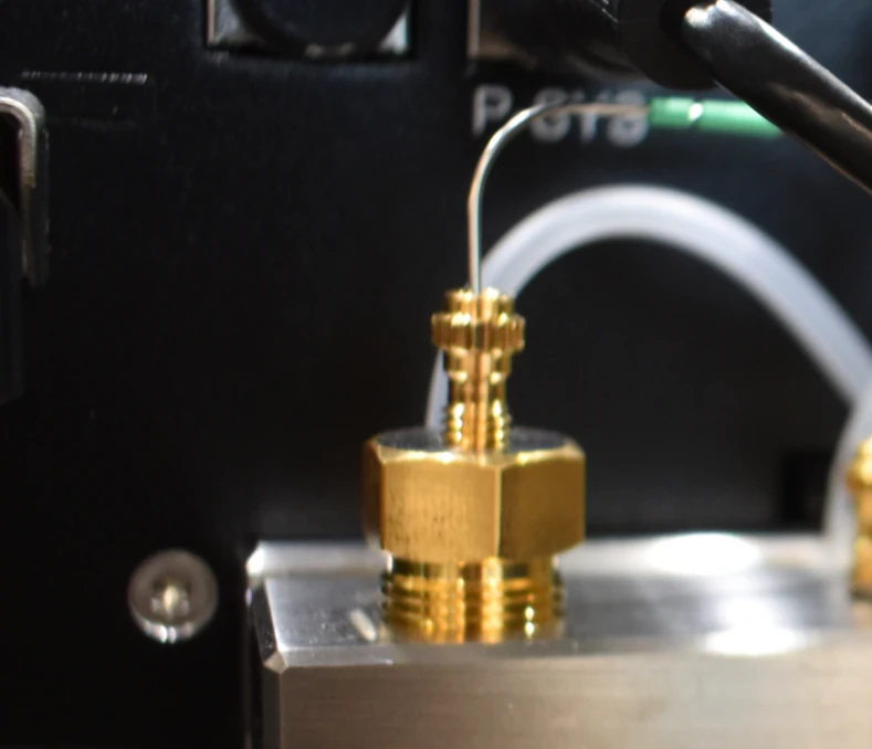
A Technical Guide to Leak Elimination, Flow Integrity, and Long-Term Chromatographic Reliability
Why HPLC Micro-Leaks Matter in Analytical Practice
HPLC micro-leaks—small, often invisible leaks at fittings, unions, or ports—are among the most underestimated causes of chromatographic instability. Unlike catastrophic leaks, micro-leaks may not trigger alarms or obvious pressure loss, yet they progressively degrade system performance and data integrity.
Key impacts include:
Air ingress and micro-bubble formation, leading to baseline noise, pressure ripple, and retention time drift.
Solvent evaporation at fittings, concentrating buffer salts and forming crystalline residues (“salt creep”) that further compromise seals and seats.
Gradient distortion:
Upstream micro-leaks can bias solvent proportioning.
Downstream micro-leaks cause effective flow and composition errors.LC–MS instability, where even trace leaks near the ion source disrupt spray formation, increase chemical noise, and reduce sensitivity.
From a quality standpoint, unresolved micro-leaks are a common hidden contributor to poor precision, failed system suitability, and out-of-trend (OOT) results.
Common Root Causes of Persistent HPLC Micro-Leaks
Most micro-leaks trace back to improper swaging or part mismatch, rather than defective hardware. Frequent causes include:
Under-tightened ferrules
Incomplete metal-to-metal or polymer-to-seat sealing at the port interface.Over-tightened fittings
Crushed tubing, deformed ferrules, damaged conical seats, and added dead volume.Mismatched geometry
Coned ferrules used in flat-bottom ports (or vice versa); incorrect ferrule length for port depth.Material incompatibility
PEEK cold-flow or cracking under high pressure or elevated temperature
Stainless-steel ferrules biting too aggressively into thin-wall tubingWorn or damaged port seats
Scored cones or chipped flat faces prevent uniform sealing.Tubing defects
Non-square cuts, burrs, ovalized PEEK tubing, or particulate contamination.Reused ferrules
Previously swaged ferrules rarely reseal correctly in a different port.Thread issues
Cross-threading or debris in threads prevents proper torque transfer.
Fast Diagnostic Workflow for HPLC Micro-Leaks
Safety First
Use absorbent pads beneath fittings.
Avoid ignition sources when working with high-organic mobile phases.
Wear appropriate PPE.
Rapid Triage Under Controlled Conditions
Stabilize the system isocratically (e.g., 50:50 MeOH/H₂O).
Set
Flow = 0.5–1.0 mL/min; typical pressure 100–200 bar.Inspect all fittings with a bright light and lint-free solvent-wetted swab to detect wicking.
Quantitative check (optional):
Place pre-weighed absorbent swatches beneath suspect fittings.
Reweigh after 10–30 minutes to estimate leak rate.
Isolate the Leak Source
Bypass components stepwise using zero-dead-volume (ZDV) unions:
Pump → mixer → autosampler → column → detectorPerform a pressure-hold test:
Install a blank plug downstream of the test segment.
Ramp to a safe pressure (e.g., ~200 bar).
SetFlow = 0.00 mL/min.
Stable pressure indicates integrity; decay confirms a leak.
Visual Indicators
Salt crusts or solvent sheen around nuts or ferrules
Micro-bubbles in downstream transparent tubing
Pressure ripple disproportionate to pump stroke frequency
Swaging Fundamentals: Getting the Seal Right the First Time
Components and Geometry
Common analytical HPLC fittings:
10-32 threads, 1/16″ OD tubing, coned seatsMicrobore/UHPLC systems may use:
6-40 or M6 threads, flat-bottom portsFerrule types:
Stainless steel (one- or two-piece)
Polymer (PEEK, ETFE)
Hybrid (e.g., Vespel/graphite)
Rule: Always match ferrule geometry to port geometry (coned-to-coned, flat-to-flat).
Tubing Preparation (Critical Step)
Stainless steel tubing
Cut square with a hardened cutter
Deburr ID and OD carefully
Rinse to remove metal finesPEEK tubing
Single-stroke razor cut
Avoid ovalization or compressionConfirm OD tolerance; thin-wall SS is especially sensitive to over-swaging.
Proper Swaging: Stainless-Steel Compression Fittings
Insert clean tubing fully until it bottoms in the port.
Finger-tighten the nut to resistance.
Tighten incrementally with a wrench (typically 1/8–1/4 turn).
Pressurize and inspect.
Initial swage may require additional turns; subsequent remakes usually need only ~1/8 turn.
Avoid repeated loosen/tighten cycles during first make-up—they score seats and ferrules.
Proper Swaging: PEEK / Finger-Tight Fittings
Use fittings rated for the system pressure.
Fully seat tubing and tighten finger-tight.
Only apply a minimal wrench nudge if explicitly allowed.
Re-check after the first pressure and temperature cycle due to PEEK cold-flow.
How Improper Swaging Creates Persistent Micro-Leaks
Under-tightening leaves a microscopic annulus that passes vapor and air but not bulk liquid.
Over-tightening deforms ferrules and seats; seals fail intermittently under pulsation or thermal cycling.
Ferrule transfer between ports misaligns the sealing surface, causing off-axis sealing.
Polymer creep relaxes torque over time, especially during long gradients or oven ramps.
These effects explain why a fitting may appear leak-free initially but fail hours or days later.
Systematic Leak Detection Methods
Solvent swab test: Wipe with IPA; watch for fresh wetting.
Bubble solution: Apply externally under pressure; observe bubble growth (keep away from electronics).
Fluorescent tracer: Trace dye in water; inspect under UV (flush thoroughly afterward).
Pressure decay test:
Plug downstream, ramp to ~200 bar, hold for 10 min; ≤1 bar drift indicates integrity.Gravimetric method:
Pre-weighed wipe around fitting; milligram-level gains confirm micro-leaks.Segment bypass:
ZDV unions provide definitive localization.
Fixing Persistent HPLC Micro-Leaks
Refresh the Joint
Replace ferrule(s) and nut; never reuse deformed ferrules.
Recut the last 3–5 mm of tubing; deburr and clean.
Reswage following best practice.
Match Parts Correctly
Use the correct ferrule profile for the port.
For deep or nonstandard ports, use manufacturer-specific adapters.
Address Seat Damage
Inspect seats with magnification for scoring or chips.
Lightly lap coned seats if tools are available; otherwise replace the component.
Control Torque
Use torque-limiting wrenches for stainless 10-32 fittings where possible.
Follow finger-tight guidance strictly for polymer fittings.
Stabilize Upstream Conditions
Degas and re-prime solvent lines (
Prime A/B, thenPurge).Verify check valve integrity; rebuild or replace if air ingestion persists.
Mechanical and Environmental Control
Secure tubing to prevent vibration or bending stress.
Minimize thermal cycling; solvent vapor buildup accelerates creep.
Preventive Practices and SOP Elements
Standardize fitting types and geometries across instruments.
Maintain a swaging SOP:
Incremental tightening with pressurized checks
No ferrule reuse or port-to-port transferProvide hands-on training using sacrificial fittings.
Inspection cadence:
Weekly: visual leak checks
Monthly: pressure-hold testsKeep consumables on hand: ferrules, nuts, ZDV unions, blank plugs.
Match materials to pressure, temperature, and solvent compatibility.
Detector-Specific Considerations
UV/Vis: Oxygen ingress increases baseline drift at low wavelengths and spike noise from bubbles.
RI detectors: Extremely sensitive; even minute leaks cause unstable baselines.
Fluorescence: Composition changes affect quenching and linearity.
LC–MS: Any leak near the sprayer destabilizes nebulization and increases background.
Quick Reference Checklist
Tubing cut square and clean?
Correct ferrule material and geometry?
Tubing fully bottomed before tightening?
Tightened incrementally and verified under pressure?
No ferrule reuse?
Seat intact or properly remediated?
Pressure-hold and swab tests passed?
Summary
Improper swaging is one of the primary root causes of persistent HPLC micro-leaks. Correct geometry matching, meticulous tubing preparation, controlled torque during first make-up, and disciplined verification under pressure eliminate most issues. When leaks persist, replace ferrules, refresh tubing ends, and inspect or remediate port seats. A structured isolation strategy combined with quantitative leak checks ensures durable, reproducible fixes.