Injector Leaks in HPLC and Associated Pressure Loss
Quick diagnostic guide for Injector Leaks in HPLC and Associated Pressure Loss: common causes and practical remedies to restore normal pressure.
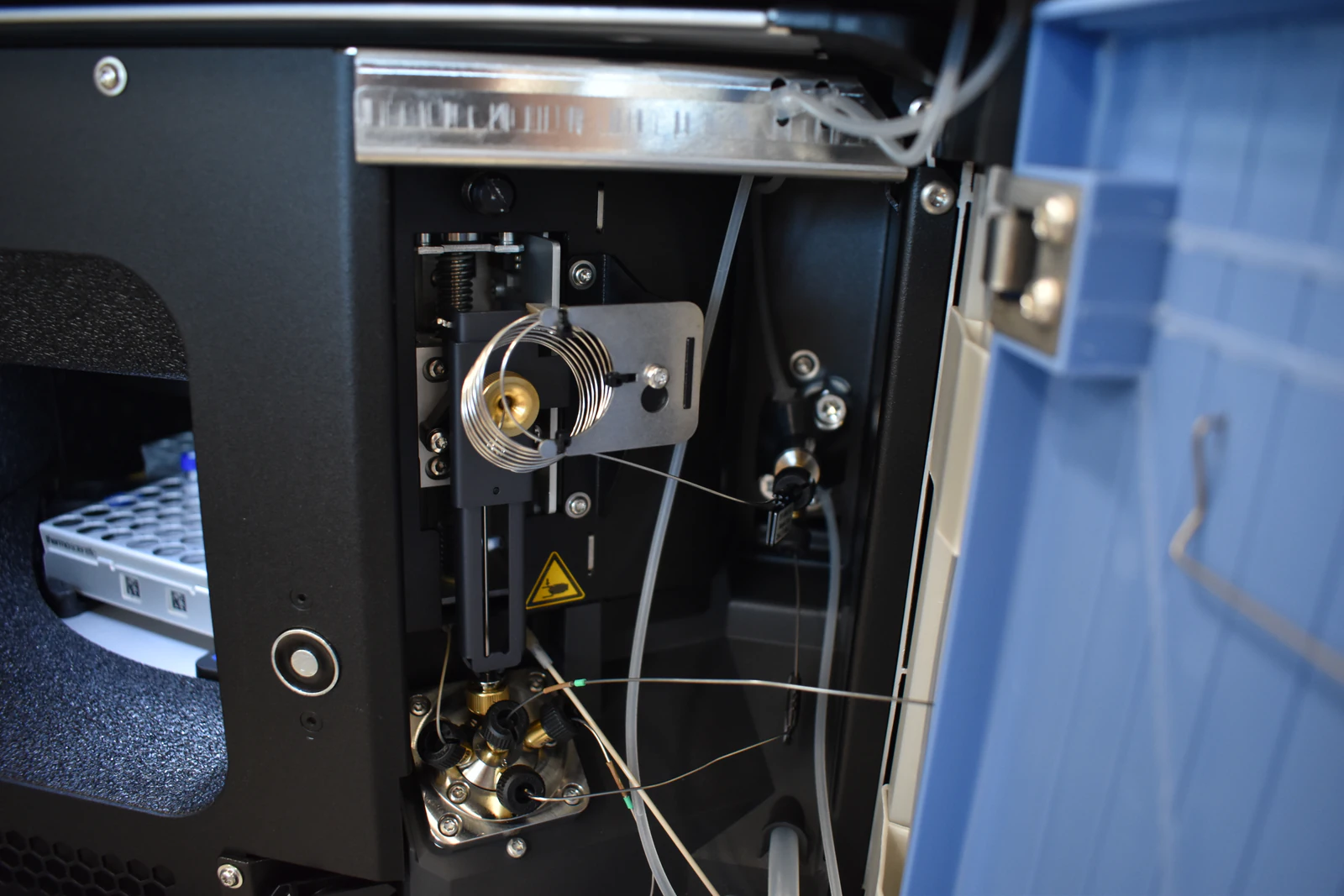
Injector Leaks in HPLC and Associated Pressure Loss
Mechanisms, Diagnostics, Chromatographic Symptoms, and Corrective Actions
Executive Overview
High-Performance Liquid Chromatography (HPLC) systems depend on a fully sealed, high-pressure fluidic pathway to deliver accurate flow, reproducible gradients, and stable chromatographic performance. The injector assembly—whether a manual valve or an autosampler-driven multiport rotary valve—is one of the most common locations for leaks on the high-pressure side of the system.
Injector leaks divert mobile phase away from the column, resulting in reduced delivered flow, lower measured backpressure, and systematic degradation of chromatographic performance, including retention time shifts, peak distortion, sensitivity loss, and poor injection repeatability. This article explains how injector leaks form, why they cause pressure loss, how to diagnose them unambiguously, and how to correct and prevent them in routine and UHPLC operation.
Injector Architecture and Where Leaks Arise
Understanding injector construction is essential for diagnosing pressure anomalies.
Core Injector Components
Multiport high-pressure valve
Typically a six-port (or ten-port) rotary valve consisting of:
A rotor seal (polymeric or composite) that rotates against
A stator face (hardened stainless steel or ceramic) containing fluidic ports.Sample loop and capillaries
Fixed-volume loop with inlet/outlet tubing and high-pressure fittings.Autosampler needle and needle seat
Creates a sealed interface during aspiration, dispense, and loop loading.
Operating Positions
Load position
Pump mobile phase flows directly to the column through a dedicated high-pressure path.
Sample loop is filled at low pressure via the autosampler.Inject position
The sample loop is placed inline with the pump flow and swept onto the column.
Typical Leak Locations
External leaks
Wet fittings, visible drips, salt crusts at valve ports, loop fittings, or needle seat.Internal bypass leaks
Mobile phase short-circuits across worn rotor seal tracks or a damaged stator face.
No visible solvent loss; flow is diverted internally.Needle seat leaks
Damaged or contaminated seat/O-ring allows solvent or sample to escape during or after injection.
Why Injector Leaks Cause Pressure Loss
In most HPLC systems, the pressure transducer is located at or near the pump outlet. The displayed pressure reflects the sum of pressure drops across all downstream components, including tubing, injector, and column.
When a leak occurs downstream of the pressure sensor:
A parallel flow path is created.
Part of the pump flow bypasses the column through the leak.
Because column backpressure is approximately proportional to flow under laminar conditions, less flow through the column produces lower measured pressure.
Practical Flow Split Approximation
If system pressure drops unexpectedly at constant flow, the effective column flow can be estimated:
[
Q_{\text{eff}} \approx Q_{\text{set}} \times \frac{P_{\text{meas}}}{P_{\text{ref}}}
]
[
Q_{\text{leak}} \approx Q_{\text{set}} - Q_{\text{eff}}
]
Example
Q_set = 1.00 mL/minP_ref = 200 bar(normal)P_meas = 150 bar(observed)
→ Q_eff ≈ 0.75 mL/min
→ Q_leak ≈ 0.25 mL/min
Internal rotor-seal bypass leaks behave identically to hidden flow splitters, altering effective gradient delivery, retention behavior, and quantitative accuracy without visible solvent loss.
Chromatographic Symptoms Associated with Injector Leaks
Pressure and Flow Indicators
Lower-than-expected backpressure at constant flow.
Pressure instability or oscillation if leak rate varies with valve position.
Different pressures observed in Load vs Inject positions.
Retention and Separation Effects
Isocratic methods
Reduced column flow typically increases retention times.Gradient methods
Shallower effective gradient at the column.
Delayed elution and broadened peaks.
Peak Shape and Quantitation
Peak tailing or fronting due to added dead volume or partial sample loss.
Broader peaks from dispersion around damaged sealing interfaces.
Reduced peak areas and poor injection %RSD.
Variable carryover when the needle seat fails to seal consistently.
Secondary Effects
Increased baseline noise or gradient irregularities.
Bubble formation or cavitation near leaking interfaces.
Inconsistent MS response in LC–MS workflows.
Common Root Causes and Failure Modes
Rotor seal wear
Grooving, flattening, or chemical degradation.Stator face damage
Scratches, pitting, or embedded particulates.Needle seat damage
Chipping, erosion, salt crystallization, or O-ring failure.Improper fittings
Overtightened PEEK ferrules, cracked fittings, misaligned tubing.Particulate abrasion
Insufficient mobile phase filtration or buffer precipitation.Solvent/material incompatibility
Strong solvents, extreme pH, or elevated temperatures degrading polymers.Excessive mechanical stress
High actuation frequency, excessive torque, dry valve operation.Thermal cycling
Differential expansion compromising seal integrity.
Diagnostic Workflow (Step-by-Step)
Safety first: Always depressurize before loosening fittings. Wear appropriate PPE and contain solvents.
1. Establish a Pressure Baseline
Record normal pressure at known flow using a healthy column or restrictor.
2. Visual Leak Inspection
Inspect valve body, ports, and needle seat for wetness or salt residue.
Use lint-free tissue to detect slow weeping leaks.
3. Load vs Inject Pressure Test
Toggle valve position at constant flow:
Pressure drop only in Inject → rotor seal, stator face, or loop path.
Pressure low in both → fitting or needle seat in main flow path.
4. Injector Bypass Test
Replace injector with a union (pump → column).
Pressure recovery confirms injector as the fault source.
5. Restrictor Isolation Test
Remove column, install known restrictor after injector.
Low pressure indicates internal bypass leakage.
6. Pressure Hold (Decay) Test
Pressurize to ~100 bar at low flow.
Stop flow and monitor decay; rapid loss indicates leakage.
Switch valve positions to localize.
7. Needle Seat Evaluation
Observe seat area after injection for droplets or residue.
8. Dye-Tracing (Optional)
Use a dilute colored aqueous solution to reveal external leaks.
Flush thoroughly afterward.
Corrective Actions
Rotor Seal and Valve Service
Replace rotor seal when pressure differs by valve position or lifetime is exceeded.
Inspect stator face; replace if scratched or pitted.
Condition new seals at low flow in both positions.
Needle and Seat Maintenance
Replace worn needles and seats.
Remove salt and particulate buildup.
Verify autosampler alignment to avoid side loading.
Fittings and Tubing
Reseat or replace ferrules and fittings.
Use correct tubing OD and square cuts.
Apply manufacturer-specified torque only.
Cleanliness and Filtration
Install inline and precolumn filters (typically 0.2 µm).
Flush buffers with water, then organic solvent before shutdown.
Method and Solvent Controls
Confirm solvent compatibility with injector materials.
Avoid prolonged extremes of pH, temperature, and swelling solvents.
Use controlled pressure ramps to reduce seal stress.
System Re-Qualification
Verify pressure vs flow using a restrictor.
Re-run system suitability: retention time, plate count, tailing, injection %RSD.
Preventive Maintenance Best Practices
Scheduled Replacement
Rotor seals: every 6–12 months (more frequently for UHPLC).
Needle seats and syringes: based on injection count.
Operating Discipline
Filter and degas all mobile phases.
Never allow buffers to dry in the injector.
Flush thoroughly after buffered methods.
Mechanical Care
Use correct fitting torque.
Avoid unnecessary valve actuation.
Keep spare seals, seats, and fittings available.
Documentation
Track pressure vs flow trends.
Log leak events and component replacements.
Special Considerations
UHPLC Systems
Small leaks cause large performance losses at >600 bar.
Use UHPLC-rated seals, fittings, and minimal dead volume.
Low-Pressure Mixing Systems
Injector leaks distort delivered gradients.
Re-verify gradient delay volume after injector service.
Bio-Inert Flow Paths
Confirm solvent compatibility with PEEK and polymeric components.
Use ceramic or sapphire seats when required.
Brief Summary
Injector leaks—whether external or internal—divert flow away from the column, reducing measured backpressure and compromising chromatographic performance. The most common causes are worn rotor seals, damaged stator faces, faulty needle seats, and compromised fittings. Reliable diagnosis uses Load/Inject pressure comparisons, bypass tests, and pressure decay measurements. Corrective maintenance and disciplined solvent handling restore performance and prevent recurrence.