UV Baseline Spikes from External Electrical Interference
Fix UV Baseline Spikes from External Electrical Interference: common causes and practical remedies to reduce baseline noise. separate fluid-path vs detector/electrical causes.
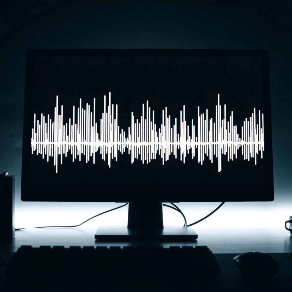
Mechanisms, Diagnosis, Troubleshooting, and Mitigation for Stable UV Detector Performance
Executive Overview: Why UV Baseline Spikes Matter
Ultraviolet (UV) detectors used in HPLC (High-Performance Liquid Chromatography) and UV-Vis spectroscopy depend on highly stable photometric measurements. External electrical interference (EMI/RFI) can inject transient disturbances into detector electronics, producing sharp, non-chemical baseline spikes.
These artifacts:
Distort chromatographic baselines
Complicate peak integration
Impair quantitative accuracy
Mask low-level analyte signals
Reduce method robustness
Understanding the mechanisms of electrical interference, recognizing the characteristic signatures, and implementing structured diagnostic and mitigation strategies are essential for maintaining analytical data integrity.
Fundamentals of UV Detector Electronics and Susceptibility to Noise
UV detectors convert light intensity into electrical signals through a multi-stage process:
Photodiode generates current proportional to transmitted light.
A high-gain transimpedance amplifier (TIA) converts current to voltage.
Signal conditioning and filtering occur.
Analog-to-digital conversion produces the digital chromatogram.
The fundamental conversion relationship is:
[
V_{out} = - I_{photo} \times R_f
]
Where:
( V_{out} ) = output voltage
( I_{photo} ) = photodiode current
( R_f ) = feedback resistor of the transimpedance amplifier
Because ( R_f ) is large (high gain), even very small induced currents from electromagnetic disturbances produce measurable voltage spikes.
High input impedance and wide bandwidth make this stage inherently sensitive to:
Fast transient electrical noise
High-frequency switching ripple
Ground potential differences
In ratioing detectors (sample/reference channel systems), common-mode noise may partially cancel. However, fast nonuniform disturbances still produce detectable spikes.
How External Electrical Interference Produces UV Baseline Spikes
Electrical interference enters UV detector systems through several well-understood physical coupling mechanisms.
1. Radiated Coupling (EMI/RFI)
Time-varying electromagnetic fields induce voltages in:
Signal wiring
Detector circuit traces
Lamp power supply lines
Sources include:
Variable-frequency drives (VFDs)
Motors
Electronic ballasts
RF transmitters
2. Conducted Coupling
Noise travels along:
Mains power lines
Ground conductors
Communication cables
It enters the detector through the power supply or interface ports.
3. Ground Loops
Multiple ground paths at different potentials create circulating currents. These convert common-mode noise into differential voltage spikes within sensitive amplifier stages.
4. Capacitive and Inductive Coupling
Nearby switching devices generate high dV/dt or dI/dt transients that couple into adjacent cables via:
Electric field (capacitive) coupling
Magnetic field (inductive) coupling
5. Lamp Power Supply Ripple
Switching ripple or modulation in the lamp supply can directly alter:
Lamp intensity
Reference channel stability
This produces synchronous baseline spikes.
Characteristic Signatures of Electrical Interference Spikes
Electrical interference produces a distinctive pattern that differentiates it from chemical or chromatographic artifacts.
Typical features:
Very narrow excursions (milliseconds to a few hundred milliseconds)
High slope, non-Gaussian peak shape
Amplitude from a few mAU to hundreds of mAU
Persistence across wavelengths (e.g., 254 nm and 280 nm)
Occurrence with:
Flow = 0
Blank mobile phase
Blocked flow cellCorrelation with facility equipment operation
Simultaneous spikes across multiple detectors or channels
Insensitivity to:
Gradient profile
Column chemistry
Temperature settings
If spikes occur under no-flow, blank conditions, the root cause is almost certainly electrical rather than chemical.
Common Laboratory Sources of UV Electrical Interference
Analytical laboratories contain numerous high-interference devices:
Variable-frequency drives (HVAC blowers, pumps)
Switched-mode power supplies (computers, monitors, chargers)
UPS systems (line-interactive mode)
Fluorescent lighting with electronic ballasts
LED drivers
Refrigerators and freezers
Autoclaves and ovens switching large loads
Centrifuges and shakers
Elevator motors
Large compressors
RF devices (two-way radios)
These sources may share electrical distribution pathways with analytical instrumentation.
Structured Diagnostic Workflow for UV Baseline Spikes
A systematic approach is essential for accurate diagnosis.
Step 1: Establish a Chemical Baseline Control
Run:
flow = 0lamp = ONcell = clean or blocked
Record at two wavelengths (e.g., 254 nm and 280 nm).
If spikes persist, they are non-chemical.
Step 2: Power and Ground Testing
Move detector to a dedicated circuit.
Verify earth ground integrity.
Test using:
Online double-conversion UPS
Isolation transformerTemporarily power from a different branch circuit.
If spike frequency changes, conducted interference is confirmed.
Step 3: Temporal Correlation
Log spike timestamps.
Compare with:
HVAC cycles
Elevator activity
Refrigeration compressor cycling
Lighting switching events
Correlated timing strongly implicates facility sources.
Step 4: Cable and Layout Inspection
Reroute signal cables away from motors and VFDs.
Avoid parallel runs with power cables.
Verify shield integrity.
Ensure shield termination to chassis at one end only.
Step 5: Instrument Isolation
Disconnect nonessential USB and Ethernet cables.
Pause autosampler and pump operation.
Monitor analog output with an oscilloscope to visualize transient frequency and duration.
Step 6: Configuration Testing
Evaluate:
Sampling rate
Time constant
Digital averaging
Reference channel ratioing
Improved cancellation suggests common-mode interference.
Mitigation Strategies for UV Baseline Electrical Noise
Apply layered mitigation from facility to data level.
Facility-Level Controls
Dedicated, bonded earth ground (star-ground topology)
Separate instrument circuits from heavy loads
Install EMI/RFI line filters
Use online double-conversion UPS
Install isolation transformers
Instrument-Level Controls
Verify chassis grounding
Tighten internal ground straps
Use shielded twisted-pair cables
Install ferrite chokes near instrument inputs
Replace lamp power supplies exhibiting ripple
Enable reference channel ratioing
Moderately increasing the detector time constant may reduce spike amplitude without distorting chromatographic peaks.
Layout and Operational Practices
Maintain physical separation from high-noise devices
Route cables orthogonally relative to interference sources
Avoid daisy-chained power strips
Use grounded, filtered distribution units
Schedule runs during low-facility-activity periods if necessary
Data Processing (Last Resort)
Only if electrical correction is incomplete:
Apply median filtering with small window (≤ 3–5 points)
Use slope- and amplitude-based outlier rejection
Interpolate conservatively
Avoid aggressive smoothing that alters peak shape or quantitative integrity.
Validation and Documentation
During method validation:
Establish baseline RMS noise limits
Define spike rate thresholds
Record grounding configuration
Document electrical environment
Reassess after facility modifications
Proper IQ/OQ/PQ documentation ensures traceability and regulatory defensibility.
Practical Troubleshooting Checklist
Flow = 0, Lamp ON → Are spikes present?
Change circuit or UPS → Improvement?
Add ferrite chokes → Reduced frequency?
Disable nearby VFD → Spike rate drops?
Increase time constant moderately → Stable baseline?
Verify ground integrity → Remove loops?
Inspect lamp power supply → Ripple present?
Summary: Restoring UV Baseline Stability
UV baseline spikes from external electrical interference arise from radiated and conducted electromagnetic noise coupling into high-gain detector electronics. These artifacts are:
Narrow
High-amplitude
Non-chemical
Often synchronized with facility equipment
A structured diagnostic workflow combined with layered mitigation—spanning facility grounding, power conditioning, cable routing, and careful detector configuration—reliably restores baseline stability and preserves chromatographic accuracy.