Gradient Proportioning Valve Malfunction in HPLC Pumps
Diagnose Gradient Proportioning Valve Malfunction in HPLC Pumps: common causes and practical remedies to recover sensitivity.
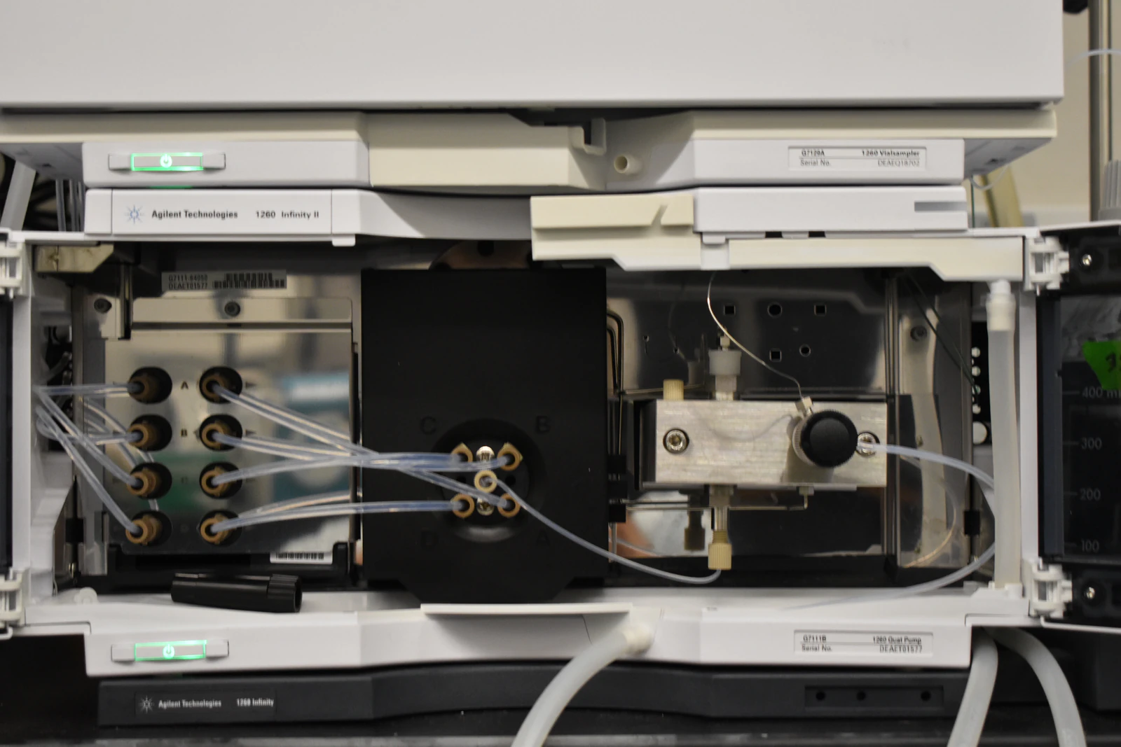
Gradient Proportioning Valve Malfunction in HPLC Pumps
Mechanisms, Diagnostics, and Corrective Actions for Low-Pressure Mixing Systems
Overview
In quaternary HPLC systems that employ low-pressure mixing (LPM), the gradient proportioning valve (GPV) is the central component that defines solvent composition. The GPV meters discrete aliquots of each mobile phase channel (A/B/C/D) upstream of the pump head, allowing the pump to aspirate a time-weighted mixture that is subsequently homogenized by the mixer.
When the GPV malfunctions, the delivered solvent composition deviates from the programmed gradient. This manifests as retention time drift, distorted gradients, baseline instability, and poor reproducibility, even when flow rate and pressure appear nominal. Because GPV faults often mimic pump, degasser, or check-valve problems, they are frequently misdiagnosed.
This guide provides a mechanistic explanation, step-by-step diagnostic workflow, and corrective and preventive strategies for identifying and resolving GPV-related failures in HPLC systems.
Technical Background and Core Concepts
Low-Pressure Mixing (LPM)
In LPM systems, solvent selection occurs before the pump head. The GPV opens and closes individual solvent channels in a timed sequence, and the pump draws the combined volume into a single pumping chamber.
Binary / High-Pressure Mixing (HPM)
In HPM systems, two independent pump heads deliver solvents that mix downstream under pressure. These systems do not rely on a GPV; therefore, GPV diagnostics do not apply.
Gradient Delay Volume (GDV)
The volume between the solvent-mixing point and the column inlet. Larger GDV delays the arrival of gradient changes at the column and amplifies proportioning errors.
Compressibility Compensation
A pump control function that corrects for solvent compressibility to maintain volumetric accuracy under pressure. Incorrect settings exacerbate GPV timing errors, particularly at low flow rates or with viscous solvents.
Rotor/Stator or Solenoid Manifold
The mechanical or electromechanical elements within the GPV that isolate solvent channels. Wear, swelling, or leakage at these interfaces causes cross-talk and incorrect solvent ratios.
Typical Symptoms of GPV Malfunction
Retention times shift progressively during gradient runs
Gradient peaks elute earlier or later than expected despite stable flow rate
Poor gradient linearity when tested with a UV tracer
Baseline oscillations or noise synchronized with valve actuation
Incomplete or slow re-equilibration to starting conditions
Channel-specific delivery errors (one solvent under- or over-delivered)
Unexpected solvent cross-contamination between channels
Persistent bubbles or priming difficulty isolated to specific solvent lines
These symptoms often persist even when the column is bypassed, indicating an upstream fluidics issue.
Rapid Triage Checklist
Before detailed diagnostics, confirm the following:
The system is a quaternary low-pressure mixing pump
Solvents are fresh, miscible, filtered, and properly degassed
Degasser vacuum level is within specification
Solvent inlet frits are clean and fully submerged
Inlet tubing is unkinked and leak-free
Each channel can be primed independently without cavitation
If issues persist after these checks, proceed with targeted GPV diagnostics.
Diagnostic Workflow
1. Channel-by-Channel Gravimetric Delivery Test
Purpose: Verify that each solvent channel delivers the commanded volume.
Procedure:
Set
PURGEor high-flowPRIME(e.g., 5.0 mL/min)Run one solvent channel at a time
Collect effluent for a fixed interval (e.g., 60 seconds)
Convert mass to volume using solvent density
Compare measured delivery to expected volume
Interpretation:
Deviations > ±2% suggest proportioning errors, inlet restriction, or GPV leakage
Channel-specific deviations strongly implicate the GPV or inlet hardware
2. Gradient Composition Accuracy Test (UV Tracer)
Purpose: Assess gradient linearity and timing.
Procedure:
Mobile phase A: water
Mobile phase B: water with 0.1% acetone (UV tracer)
Program a linear gradient (e.g., 0–100% B over 10–20 min)
Bypass the column or use a short restrictor
Monitor UV absorbance at ~254–265 nm
Expected outcome:
Linear UV signal increase proportional to programmed %B
Abnormal findings:
Steps, plateaus, hysteresis, or curvature indicate GPV timing errors, internal leakage, or mixer problems
3. Degassing and Air Entrapment Evaluation
Confirm degasser vacuum stability
Observe inlet lines during priming for persistent bubbles
Temporarily bypass the degasser to determine whether it is introducing restriction or air
Air in LPM systems disproportionately affects GPV accuracy because compressible gas disrupts timed volumetric aspiration.
4. Static Leak and Cross-Talk Screening
Introduce a tracer (UV or dye) into one channel only
Leave other channels filled with tracer-free solvent
Monitor for breakthrough into non-selected channels
Any cross-talk indicates rotor/stator wear or internal GPV leakage.
5. Valve Actuation and Timing Verification
Run GPV diagnostics or service routines if available
Listen for consistent actuation sounds
Monitor channel status indicators
Irregular cycling suggests solenoid failure, control timing drift, or mechanical binding.
6. Exclude Check-Valve Artifacts
Prime individual channels and observe pressure behavior
Swap inlet check valves or channels
If the symptom follows the check valve rather than the channel, the GPV is not the primary fault
7. Mixer and Gradient Delay Volume Assessment
Inspect mixer for blockage or channeling
Measure GDV using a step change in UV tracer
Excessive or inconsistent GDV can mimic GPV lag or poor re-equilibration
Root Causes and Mechanistic Explanation
Air entrainment: Compressible gas disrupts timed solvent aspiration
Clogged inlet frits: Unequal suction biases channel delivery
Rotor/stator wear: Internal leakage causes cross-talk and composition drift
Chemical incompatibility: High-pH buffers, DMSO, or halogenated solvents swell elastomers
Salt crystallization: Precipitates cause sticking and partial blockage
Incorrect compressibility settings: Timing errors increase at low flow or high viscosity
Firmware or configuration drift: Control logic no longer matches hardware behavior
Corrective Actions
Remove Air and Restore Inlet Integrity
Replace inlet frits
Tighten fittings and replace worn ferrules
Prime channels until bubble-free
Service degasser membranes or vacuum pump as needed
Clean Fluidic Components
Flush sequentially: water → methanol → IPA → water
Avoid aggressive chemicals unless manufacturer-approved
Never allow buffers to dry in the GPV
Replace Worn Hardware
Install new rotor/stator or solenoid manifold if cross-talk is confirmed
Replace inlet and outlet check valves if stick-slip behavior persists
Use solvent-compatible seal materials (e.g., FFKM where required)
Recalibrate and Verify
Run GPV calibration routines
Confirm compressibility settings for current solvents
Re-run UV tracer gradient to document restored linearity
Optimize Method and Configuration
Reduce unnecessary tubing to minimize GDV
Increase mixer volume for low-flow or steep gradients
Consider pre-mixed solvents for ultra-low-flow or highly sensitive separations
Preventive Maintenance Practices
Use high-purity, filtered solvents
Flush buffers daily with water followed by organic solvent
Replace inlet frits on a defined schedule
Log periodic UV tracer gradient tests
Verify degasser performance quarterly
Keep firmware and configuration tables current
Acceptance Criteria (General Guidance)
Channel delivery accuracy: within ±1–2%
UV tracer gradient linearity: R² ≥ 0.995 under controlled testing
Stable pressure trace with minimal ripple
No detectable channel cross-talk
Always compare results to the manufacturer’s specifications for your instrument model.
Summary
Gradient proportioning valve malfunction is a frequent but under-recognized cause of gradient inaccuracy, retention time drift, and baseline instability in quaternary HPLC systems. The most common contributors are air entrainment, fouled inlet hardware, rotor/stator wear, chemical incompatibility, and incorrect compressibility settings. A structured diagnostic approach—combining gravimetric testing, UV tracer gradients, degasser verification, and cross-talk screening—allows definitive identification of GPV faults. Corrective actions focused on restoring inlet integrity, replacing worn components, recalibrating proportioning, and validating gradient performance reliably return the system to specification.