How do I tell whether the column is failing versus the system being contaminated?
This guide explains how to distinguish column degradation from system contamination using diagnostic tests and observations.
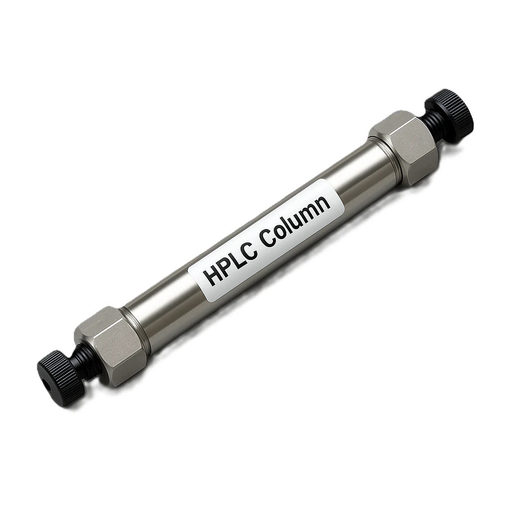
A Stepwise Diagnostic Workflow for HPLC/UHPLC and GC
When chromatographic performance suddenly degrades—ghost peaks, retention drift, lost resolution, rising backpressure—the fastest way to reduce downtime is to answer one question early:
Is the problem following the column, or is it coming from the system?
Misclassifying the source has predictable consequences. If you assume the column is “dead” when the system is contaminated, you will replace columns repeatedly without fixing the root cause. If you assume contamination when the stationary phase is failing, you can waste days on cleaning protocols while resolution continues to deteriorate.
This guide provides a rigorous, practical decision process to separate column-intrinsic failure (stationary phase deterioration, voids, irreversible fouling) from system contamination (solvents, lines, injector, mixer, detector, inlet hardware).
What “Column Failure” and “System Contamination” Mean in Practice
Column failure or column-driven problems
These originate within the column assembly (bed + frits + stationary phase chemistry), including:
Loss of efficiency: broader peaks, fewer plates, reduced resolution
Persistent peak shape distortion: tailing/fronting across standards and samples
Systematic retention changes: multiple analytes shift together under identical conditions
Pressure behavior tied to the column: progressive pressure rise (fouling) or sudden pressure drop with distortion (void/bed collapse)
Limited recoverability: washing may help, but performance does not return to baseline if chemistry/bed is damaged
System contamination or system-driven problems
These originate in solvents, plumbing, injector pathways, mixers, or detectors:
Ghost peaks in blanks (especially gradient blanks)
Carryover after high injections that decays across subsequent blanks
Baseline artifacts: steps, spikes, drift that repeat at specific gradient times or temperature program points
Selective or run-dependent issues: worse after certain samples or injections; better in direct-flow tests
Good columns still look bad until the system is cleaned, solvents refreshed, or injector/detector issues are corrected
Fast Triage: 5-Minute Decision Screen (LC-Focused)
Use these quick tests before doing anything invasive:
Run a solvent blank using the same method
Ghost peaks in blanks strongly indicate system contamination or carryover mechanisms.Inject a system suitability standard (clean matrix)
If peaks broaden and retention/efficiency degrade across multiple probes, suspect column failure or severe upstream restriction affecting the column.Bypass the column with a zero-dead-volume union
If baseline artifacts or ghost peaks persist with no column installed, the source is system-side.Remove or replace guard column / inline filter
Immediate improvement points to inlet-side fouling (often sacrificial guard/filter), not necessarily irreversible analytical column failure.Replace mobile phases and wash solvents with fresh preparations
If performance returns quickly, suspect solvent/bottle contamination or aged buffer effects rather than the column.
GC note: For GC systems, the fastest “system contamination triage” often starts with liner + septum replacement and a short stabilization run. If ghost peaks disappear, the “column failure” diagnosis is usually premature.
Controlled Diagnostic Tests (The Definitive Workflow)
The goal is to build evidence that performance follows either the column or the system. Run the tests in this order to minimize time and avoid creating new variables.
1) Blank and Carryover Challenge: Is It Injection Path Memory?
LC carryover sequence
Run:
High-concentration standard → Blank 1 → Blank 2 → Blank 3
Interpretation:
Ghost peaks that decay across blanks = classic carryover (needle seat, rotor seal, sample loop, wash solvent weakness)
Ghost peaks that recur at the same gradient time even without injection = likely system/solvent line contamination or mixer memory
High-value follow-up:
Increase needle wash strength and volume (use a wash solvent that is meaningfully stronger than the mobile phase at the time the contaminant elutes).
If ghost peaks drop sharply, the contamination is concentrated in the injection pathway.
GC carryover sequence
Run:
High-level standard → multiple solvent blanks
Interpretation:
Decaying carryover implicates liner, septum region, syringe, or inlet contamination. Column failure is less likely if the effect is strongly “history dependent.”
2) Column Bypass with Restrictor: Does the Artifact Exist Without the Column?
A key LC principle: you cannot interpret baseline behavior properly if pressure collapses to near zero after removing the column. Use a restrictor (or a short capillary line) so the pump and detector operate under a representative load.
Procedure:
Replace the column with a zero-dead-volume union
Add a capillary restrictor (or equivalent) to approximate typical system backpressure
Run the same method (including gradient blank if relevant)
Interpretation:
Artifacts persist with union/restrictor = system contamination or system malfunction
Artifacts disappear with union/restrictor but return with the column installed = column/guard/frit contamination or column damage
If you have access to a known-good column of the same chemistry, this is the fastest “tie-breaker.” If the behavior disappears with the known-good column, your original column is the likely source.
3) Guard Column and Inline Filter Challenge: Is the Restriction or Contamination at the Inlet?
Many “column failures” are actually sacrificial protection components doing their job.
Procedure:
Remove or replace the guard column and/or precolumn inline filter
Re-run the system suitability standard and compare:
pressure
peak width
tailing
retention time
Interpretation:
Immediate improvement = inlet fouling, often reversible at the guard/filter level
No improvement = fouling/damage may be within the analytical column bed or elsewhere in the system
Practical note: If pressure improves but efficiency does not fully recover, you may have both guard loading and early-stage column head fouling.
4) Fresh Solvents and Bottle Hygiene: Eliminate Reservoir and Mobile Phase Memory
Solvent contamination is frequently underestimated, especially when:
buffer mobile phases are older
reservoirs were topped up repeatedly
caps/liners leach
glassware was not dedicated or thoroughly cleaned
wash solvent bottles were neglected
Procedure:
Prepare fresh A/B (and needle wash) using clean containers and caps
Filter/degass as appropriate to your routine
Purge/prime each line so old solvent is fully displaced
Interpretation:
If the problem resolves immediately after a solvent refresh, the column is rarely the root cause.
5) Probe Mixture with Metrics: Quantify Whether the Column Chemistry/Efficiency Has Changed
The most defensible way to claim column deterioration is with measured performance metrics, not impressions.
Use a standardized probe concept:
a neutral hydrophobic probe (retention strength indicator)
an acidic and a basic probe (surface activity / interaction sensitivity)
a dead-time marker (for k′ calculations)
Evaluate:
Plates (N): broad, systematic N loss indicates efficiency decline
Tailing/asymmetry: systematic tailing across probes suggests active sites, fouling, or chemistry change
Retention factor (k′): if multiple analytes lose retention together under identical mobile phase conditions, it suggests a chemistry/phase issue rather than random contamination
Interpretation patterns:
Neutral + charged analytes all shift similarly: suspect column chemistry change or method/mobile phase composition change
Only basic analytes tail heavily: often active site issues, contamination, or endcapping/chemistry degradation (LC)
k′ shifts mainly in one direction across all peaks: check for composition delivery errors before condemning the column
6) Gradient/Program Diagnostics: Do Artifacts Occur at Specific Method Points?
LC gradient blanks
If ghost peaks appear at reproducible times without injection, suspect contamination in:
solvent channels (A vs B)
mixer/static mixer
degasser/pump pathways with memory effects
plasticizers/extractables in solvent contact materials
A powerful localization trick:
swap or isolate A and B channels (run isocratic holds using each channel independently) and see if the artifact follows a specific channel.
GC temperature programs
If ghost peaks correlate strongly with temperature ramps/holds:
column contamination may be present (high-boilers eluting during ramp)
inlet contamination can also create repeatable “program-linked” artifacts
A controlled bake-out can reduce contamination-related artifacts. If peak shapes and efficiency remain poor afterward, true column damage becomes more plausible.
7) Pressure and Flow Trends: Use Pressure as a Localization Signal (LC)
Column-linked indicators:
gradual pressure rise + increasing peak broadening = column/guard loading, often inlet-side fouling
sudden pressure drop + severe tailing/fronting = possible void/bed disruption
System-linked indicators:
pressure ripple or oscillation unrelated to viscosity changes = pump/check valves/degassing issues more than column issues
Pressure trends become decisive when paired with the bypass and guard/filter swap tests.
8) Detector and Downstream Isolation: Confirm the Detector Is Not the Culprit
A restricted flow cell or downstream regulator can cause:
apparent pressure changes
baseline disturbances
extra-column effects that look like “bad chromatography”
Procedure:
Replace the detector flow cell with a union (where feasible)
Flush the cell with a strong miscible solvent to clear films/particulates
Re-run blanks and standards
If baseline problems disappear when the detector is bypassed, the column should not be blamed.
Decision Criteria: Column Failure vs System Contamination
More consistent with column failure
Persistent efficiency loss (lower N, worse resolution) on clean standards
Broad peak shape issues across analytes
Retention loss across multiple probes under identical conditions
Pressure anomalies that follow the column (vanish when removed; return when installed)
Minimal or no ghost peaks in blanks once system is confirmed clean
More consistent with system contamination
Ghost peaks in solvent blanks or gradient blanks
Carryover that decays across sequential blanks and improves with stronger wash routines
Baseline artifacts that persist with the column removed (union/restrictor in place)
Rapid improvement after solvent refresh, injector cleaning, detector cell cleaning, or line flushing
Remediation: What to Do Once You Localize the Source
If the column is the primary issue
Replace guard/inline filter first and re-test (inlet fouling can masquerade as column failure)
Perform a controlled column wash sequence appropriate to the stationary phase and compatibility
Consider reverse-flushing only when the column design permits it
If you suspect voiding, bed collapse, or irreversible chemistry loss, replacement is typically the correct action
If the system is contaminated
LC-focused remediation:
Replace mobile phases and wash solvents; clean or replace reservoirs/caps
Flush solvent lines and degasser channels; purge until fully displaced
Clean/replace needle seat and rotor seal as needed; strengthen wash program
Flush and/or clean detector flow cell
Inspect mixers and static mixers for deposited films or particulates
Verify pump health (prime behavior, check valves) if pressure ripple accompanies the issue
GC-focused remediation:
Replace liner, septum, and inlet seals; verify purge flows
Trim the column inlet if contamination is localized near the head
Verify traps and perform leak checks
Replace or clean syringes/wash solvents if carryover is injection-path driven
Documentation That Prevents Repeat Events
A structured diagnostic becomes far more powerful when paired with good traceability:
log column ID, injections, and any regeneration steps
record solvent lot changes and buffer age
archive “baseline reference” chromatograms for:
new column qualification
clean system blank
system suitability standarduse overlays to compare pre/post cleaning and to show whether the issue follows the column or system
This turns troubleshooting into evidence-based root-cause analysis rather than opinion-driven decisions.
Summary
Distinguishing column failure from system contamination is straightforward when you use a controlled sequence of tests: blanks and carryover challenges, column bypass with a restrictor, guard/filter swaps, fresh solvent hygiene, and standardized probe metrics. Column failure typically manifests as persistent losses in efficiency/retention and pressure behavior that follows the column. System contamination reveals itself through ghost peaks, carryover, and baseline artifacts that persist even when the column is removed or that resolve quickly with solvent/injector/detector cleanup.