Loss of Detector Response in Liquid Chromatography: Practical Troubleshooting Guide
Practical troubleshooting guide for partial or complete loss of detector response in liquid chromatography. Covers common causes, diagnostic checks, and corrective actions to restore signal reliability.
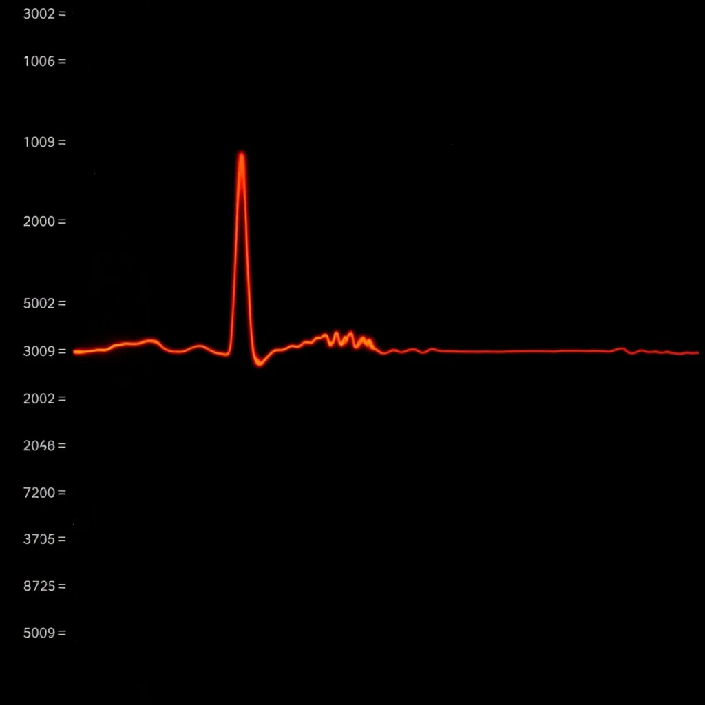
Loss of detector response in liquid chromatography (LC) is a frequent and impactful analytical problem that directly compromises sensitivity, quantitation accuracy, and data reliability. The issue may present as partial signal loss, complete disappearance of analyte peaks, or unstable detector output.
The underlying causes of detector response loss vary widely and depend strongly on the detector type, including UV-Vis, fluorescence, refractive index (RI), electrochemical detectors, and mass spectrometry systems (LC-MS/MS). Effective troubleshooting requires distinguishing between physical system issues, chemical effects, and detector-specific limitations or failures.
Symptom and Observable Problem
Loss of detector response may be observed as:
Significantly reduced peak height or peak area
Complete absence of expected analyte peaks
Inconsistent or drifting detector signal
Increased baseline noise with little or no analyte response
Poor reproducibility between injections
These symptoms can occur even when chromatographic separation and system pressure appear normal, making detector-focused diagnostics essential.
Root Cause Analysis
Detector response loss is typically caused by signal attenuation, reduced analyte mass reaching the detector, or detector sensitivity degradation. The most common causes fall into three major categories.
Physical Causes
Detector Cell Contamination or Fouling
Accumulation of particulates, precipitated buffers, or residual sample matrix within the detector flow cell can scatter light, absorb signal, or reduce effective path length. In LC-MS systems, contamination of the ion source or sampling interface reduces ionization efficiency and transmission.
Leaks and Increased Dead Volume
Small leaks at detector inlet or outlet fittings may not trigger pressure alarms but can reduce analyte mass reaching the detector. Excess dead volume at detector interfaces causes peak broadening and dilution, lowering signal intensity.
Pump or Injector Irregularities
Inconsistent flow delivery or injection volume variability reduces reproducibility and may decrease the effective amount of analyte delivered to the detector, leading to apparent sensitivity loss.
Detector Setting Drift
Incorrect wavelength selection, electronic drift, or unverified detector parameters can significantly reduce measured signal even when analyte concentration remains unchanged.
Chemical Causes
Sample Matrix Effects
Co-eluting matrix components can suppress or enhance analyte response. This effect is especially pronounced in LC-MS/MS systems, where ion suppression reduces ionization efficiency without affecting chromatographic peak shape.
Analyte Degradation or Adsorption
Analytes may degrade in the mobile phase or adsorb to tubing, fittings, or stationary phase surfaces. Both mechanisms reduce the amount of analyte reaching the detector and result in diminished response.
Mobile Phase Composition Effects
Changes in solvent composition, pH, or buffer concentration can alter detector response. For example:
UV detectors may show reduced response if the mobile phase absorbs strongly at the selected wavelength
Ionization efficiency in LC-MS may change with solvent composition or buffer additives
Detector-Specific Issues
UV-Vis Detectors
Reduced lamp intensity due to lamp aging
Flow cell contamination or altered path length
Wavelength calibration drift
Fluorescence Detectors
Incorrect excitation or emission wavelength settings
Photomultiplier tube sensitivity loss over time
Refractive Index Detectors
Temperature instability
Baseline noise caused by mobile phase mismatch or poor thermal equilibration
Mass Spectrometry Detectors (LC-MS/MS)
Ion source contamination
Suboptimal source tuning
Gas flow issues affecting nebulization and desolvation
Diagnostic Approach
A structured diagnostic workflow minimizes downtime and prevents unnecessary component replacement.
Establish Expected Baseline Response
Begin troubleshooting by confirming the expected detector response using a freshly prepared standard under known, controlled conditions.
Systematic Diagnostic Checks
Inspect and clean the detector flow cell or ion source
Verify mobile phase composition, pH, and freshness
Perform system suitability tests to confirm baseline detector performance
Review flow rate, injection volume, and pressure stability
Inspect all detector fittings for leaks or excessive dead volume
Check detector lamp status and recalibrate wavelengths if applicable
For LC-MS/MS systems, clean the source and re-optimize tuning parameters
Each diagnostic step should be followed by reinjection of a standard to confirm improvement.
Corrective Actions
Corrective actions should be implemented incrementally and validated with standard injections.
Clean or replace contaminated detector flow cells or ion source components
Reseat or replace leaking detector fittings and minimize dead volume
Restore stable flow and injection performance through pump and injector maintenance
Verify and correct detector settings, wavelengths, and calibration
Prepare fresh mobile phase using appropriate solvents and buffer concentrations
Address matrix effects through improved sample cleanup or method adjustment
Perform routine detector maintenance and system suitability checks
Related Issues
Loss of detector response is often associated with:
Poor signal-to-noise ratios
Reduced method robustness
Failed system suitability criteria
Quantitation errors and reporting inconsistencies
Increased troubleshooting frequency due to inadequate maintenance
Summary
Loss of detector response in liquid chromatography rarely originates from a single failure point. Instead, it reflects the combined effects of physical contamination, chemical interactions, and detector-specific limitations. A disciplined troubleshooting strategy—starting with baseline verification and progressing through systematic physical, chemical, and detector-specific checks—allows accurate identification of the root cause. Routine maintenance, consistent system suitability testing, and detector-appropriate optimization are essential for restoring and maintaining reliable detector performance.