Low or No HPLC Pressure Due to Pump Seal Failure
Fix Low or No HPLC Pressure Due to Pump Seal Failure: common causes and practical remedies to restore normal pressure. check flow path, filters, column, and pump health.
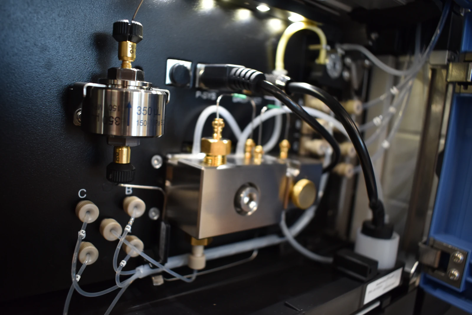
Technical Troubleshooting Guide for HPLC/UHPLC and LC–MS Pumps
When an HPLC or UHPLC system will not build pressure—or pressure is abnormally low and unstable after startup—the problem is often internal leakage in the high-pressure pump, with piston (plunger) seal failure among the most common culprits. Seal leakage reduces volumetric efficiency, prevents the pump from compressing the mobile phase effectively, and can also allow air ingress that further destabilizes pressure and flow. Buffered aqueous mobile phases accelerate failure if seal wash and shutdown flushing are not well controlled.
This guide provides a practical, instrument-agnostic workflow to confirm seal-related faults, differentiate them from similar pump issues (check valves, purge valve, air binding), and execute repair verification and prevention steps that restore pressure integrity and method robustness.
When to Suspect Pump Seal Failure
Seal failure is most likely when low pressure persists even after you have ruled out obvious issues like empty solvent bottles, open purge valves, or disconnected plumbing.
Typical patterns include:
Low or no pressure build with purge valve closed and a backpressure element installed
Pressure rises, then slowly decays at constant flow (bypassing/leakage)
Excess pressure ripple and unstable flow at steady setpoint
Frequent prime failures or repeated “cavitation-like” behavior (air drawn in through a compromised seal interface)
Visible wetness or dripping around the pump head/drain area
Salt crystals or dried residue around the pump head, seal-wash fittings, or drain (strong indicator for buffered operation)
Practical rule:
If the pump cannot “hold” pressure against a known restriction, assume internal leakage until proven otherwise.
How Pump Seals Control Pressure (Why Failure Causes Low Pressure)
Most LC pumps use a reciprocating piston that displaces liquid in a pump chamber. The piston seal must maintain a tight interface with the moving piston so that each stroke delivers liquid forward rather than leaking backward or around the piston.
Key concepts:
Volumetric efficiency: how much of the piston stroke becomes delivered flow. Leakage lowers volumetric efficiency and prevents pressure from ramping normally.
Dead-head behavior: a healthy pump rapidly reaches a high pressure limit against a closed or highly restricted outlet. A leaking seal will ramp slowly, oscillate, or fail to reach expected values.
Seal wash function (when present): flushes the piston/seal interface to prevent salt crystallization and abrasion during buffered operation.
If the seal lip is worn, extruded, chemically degraded, or the piston is scratched, the pump behaves like it has an internal bypass—flow may still occur, but pressure control becomes unreliable and often low.
Rapid Triage Before Disassembly (10–15 Minutes)
Do these checks first to avoid unnecessary pump service.
1) Verify the purge valve is truly closed
A purge valve that is slightly open can mimic seal failure by providing a low-resistance bypass to waste.
Confirm the purge valve is fully closed and seated.
If the purge valve design is manual, do not rely on “finger tight” alone—seat it consistently per your instrument practice.
2) Confirm solvent supply and inlet integrity
Bottles are sufficiently filled; pickup frits are submerged.
Inlet frits are not clogged and inlet tubing is not cracked or loose.
Degassing is functioning and solvents are reasonably bubble-free.
3) Remove the column to eliminate downstream restriction variables
Column issues generally cause high pressure, not low pressure. However, removing the column prevents misinterpretation during pump tests.
Then install one of the following:
A known backpressure restrictor appropriate for your flow rate, or
A short capillary section that produces stable backpressure, or
A union for specific tests (described below)
4) Prime with a low-viscosity, fully miscible solvent
Prime each channel until the stream is continuous and bubble-free.
Observe the pump head drain area during priming for signs of leakage.
If pressure still remains low/unstable after these steps, proceed to confirmation tests.
Confirming Pump Seal Failure: High-Confidence Tests
Test A — Visual leak and residue inspection (fast, high value)
Look for:
Active dripping from the pump head drain or beneath the pump head
Wet fittings or persistent solvent odor localized near the pump head
Salt crystals/dried buffer residue around the pump head or seal-wash region
Interpretation:
Any visible leakage from the pump head region strongly supports seal or piston issues, especially if it worsens with flow or pressure attempts.
Test B — Dead-head test (best discriminator for internal leakage)
Purpose: Determine whether the pump can generate and hold high pressure against a blocked outlet.
General concept:
A healthy pump will ramp pressure quickly toward the instrument’s pressure limit (or a high value) and hold.
A leaking pump (seal or valve) will struggle to ramp, oscillate, or fail to hold.
How to run it safely:
Remove the column and route the outlet appropriately for the test setup.
Install a “dead-head” configuration per your instrument’s safe service practice (some systems have a built-in procedure; do not improvise if your model prohibits it).
Start at very low flow (e.g., 0.1–0.2 mL/min on an analytical system) and watch the pressure response.
Interpretation:
Fast ramp + stable hold: seals are less likely; look at downstream restrictions, sensor artifacts, or other components.
Slow ramp / failure to build / unstable oscillation: internal leakage is likely (seals and/or check valves).
Important differentiation:
If you see wetness at the pump head, prioritize seals/piston.
If there is no leakage but pressure oscillates heavily, check valves can be the dominant contributor.
Test C — Static hold test with a restrictor (real-world simulation)
Purpose: Evaluate whether pressure decays under constant flow against a known resistance.
Setup:
Install a stable restrictor and run at a steady flow.
Observe pressure stability over several minutes.
Interpretation:
Pressure decays gradually while flow is commanded: internal bypassing is occurring (often seals).
Pressure pulses in a stroke-like rhythm: check valves and/or air binding may dominate.
Test D — Priming behavior and bubble cycling
Seal wear can allow air to be drawn into the pump head region, creating repeated microbubbles even with degassed solvent.
Indicators:
repeated bubble trains that reappear after apparently successful priming
prime success is short-lived; pressure becomes unstable after a brief period
Distinguishing Seal Failure from Look-Alike Problems
Seal failure is more likely when:
visible leakage or salt crust is present at/near the pump head
dead-head performance is poor (slow/failed ramp)
pressure rises then decays at constant flow against a restrictor
priming difficulty persists despite solvent and degassing corrections
Check valve problems are more likely when:
pressure pulsation is strong and periodic at stroke frequency
pressure may build intermittently, then drop in pulses
tapping/flushing temporarily changes behavior
leakage is not visible externally
Purge valve issues are more likely when:
pressure is low and stable (not necessarily noisy)
closing the purge valve more firmly changes pressure immediately
purge pathway flow remains present when it should not
In practice, seals and check valves often fail in the same operational environment (buffers, particulates), so it is not unusual to service both during a corrective maintenance cycle.
Root Causes of Seal Failure (Why It Happens)
Common mechanisms include:
Particulate abrasion
insufficient filtration of mobile phase or samples
degraded inlet frits allowing particles to reach the pumpSalt crystallization
buffered aqueous phases left stagnant
inadequate seal wash usage during buffer operation
switching from salty aqueous directly into high organic without water flushingDry starts
pump started with an unflooded pump head or air in the chamberChemical incompatibility
seal material not suitable for pH extremes or certain solventsPressure spikes and mechanical stress
abrupt flow changes into high restriction paths
recurring near-limit pressure operationLong idle periods
residues dry at the seal interface and abrade the seal lip at restart
Corrective Actions: Pump Seal Service (Step-by-Step Overview)
This is a technical overview intended to align with typical pump designs. Always follow your instrument’s specific service procedure for disassembly, seal orientation, and torque.
1) Make safe and depressurize
Stop flow and relieve pressure through an appropriate route (often purge to waste).
Disconnect the column and route lines safely to waste.
Power down if required before mechanical service.
2) Clean the exterior and assess deposits
If buffers were used, rinse external residue with water first.
Follow with a miscible solvent if needed to remove organic films.
Identify where residue is originating (seal wash fittings, drain, head interface).
3) Remove the pump head and extract seals
Use the correct seal removal tools to avoid scratching the seal bore.
Note seal orientation and any backup rings.
4) Inspect the piston carefully
Look for scratches, chips, or scoring on the sapphire/ceramic piston.
A damaged piston can destroy a new seal quickly.
Clean with lint-free materials; do not introduce fibers.
5) Install new seals and backup rings correctly
Use only manufacturer-recommended lubricants (if any).
Ensure proper orientation (pressure-side vs atmospheric-side matters).
Replace dust seals if present in your pump design.
6) Reassemble and torque correctly
Overtightening can distort components; undertightening can leak.
Reconnect seal wash lines and ensure the seal wash reservoir contains appropriate wash solvent if your method uses buffers.
7) Prime and de-aerate thoroughly
Prime with a low-viscosity miscible solvent until bubble-free.
With a restrictor in place, verify pressure rises smoothly with low ripple.
Post-Repair Qualification: Verify the Pump Is Truly Fixed
Do not stop at “pressure looks better.” Confirm performance with objective checks:
Acceptance criteria targets (typical, instrument-dependent)
Dead-head behavior: rapid pressure rise and stable hold (no spontaneous decline)
Leak-free operation: no dripping or wetness at pump head/drain during pressure operation
Flow accuracy: delivered flow within instrument specification (often ±1–2% for analytical LC)
Pressure stability: markedly reduced ripple and stable baseline pressure against a restrictor
Stable priming: no recurrent bubble cycling after successful prime
A practical approach:
Verify pressure behavior with column bypassed and restrictor installed.
Run an isocratic test with a known solvent to establish a new baseline.
Reconnect the column and confirm method backpressure matches historical behavior under identical conditions.
Prevention: Extend Seal Life and Avoid Repeat Failures
Seal life is strongly influenced by buffer habits and filtration discipline. High-impact prevention steps include:
Use seal wash for buffered/high-salt methods
keep the wash solvent fresh and flowing as designedFilter mobile phases and maintain clean reservoirs
prevent particulates from reaching the pump and check valvesAvoid dry starts
prime fully before closing purge and before applying backpressureFlush salts before shutdown
use water flush to remove buffer, then transition appropriately for storageRamp flow and pressure
avoid abrupt transitions into high restriction pathsTrack maintenance by usage
pump-hours and buffer exposure are better predictors than calendar time aloneInspect inlet frits and replace proactively
pump problems frequently begin at the solvent bottle
Frequently Overlooked Contributors (Check These Even if Seals Are Failing)
Purge valve not fully seated
Degassing issues introducing persistent gas (creates unstable pressure that complicates diagnosis)
Inlet check valve contamination occurring concurrently with seal wear
Quaternary proportioning behavior that starves one channel (appears as unstable delivery)
Summary
Low or no HPLC pressure that persists after basic solvent and purge checks is commonly caused by internal pump leakage, with piston seal failure a leading root cause—especially in buffered aqueous operation. Confirm with visual leak inspection, dead-head behavior, and pressure hold testing against a known restrictor, then replace seals and inspect the piston for scoring. After repair, verify performance with objective criteria: leak-free operation, rapid pressure build, stable pressure trace, and flow accuracy. Prevent recurrence with seal wash practices, disciplined buffer flushing, and robust filtration.