Inlet Frit Blockage and Split Peaks in HPLC Columns
Fix Inlet Frit Blockage and Split Peaks in HPLC Columns: common causes and practical remedies to improve peak shape. Includes quick checks and prevention tips.
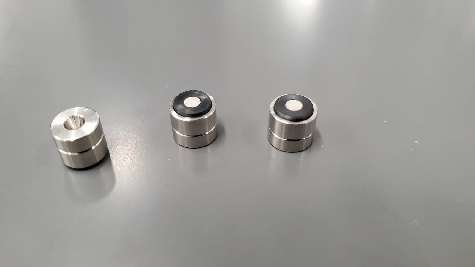
Inlet Frit Blockage and Split Peaks in HPLC Columns: A Technical Troubleshooting and Flow-Diagnostics Guide
Executive Overview
Inlet frit blockage and split peaks are closely linked failure modes in high-performance liquid chromatography. Partial obstruction at the column inlet frit disrupts the velocity profile entering the packed bed, producing nonuniform flow paths that frequently manifest as split peaks, shouldered peaks, or pronounced fronting. These effects are often accompanied by rising backpressure, loss of column efficiency, retention variability, and degraded reproducibility.
Because frit blockage commonly originates upstream of the analytical bed, rapid and structured diagnostics are essential to restore performance while minimizing unnecessary column replacement. This guide outlines symptom recognition, mechanistic causes, stepwise diagnostic tests, corrective actions, and preventive practices applicable to routine analytical workflows.
Recognizing the Symptoms
Characteristic indicators of inlet frit blockage or related flow distortions include:
A gradual or sudden increase in system backpressure, often exceeding historical baselines by a noticeable margin.
Early-eluting analytes exhibiting split peaks, shoulders, or pronounced fronting, while later-eluting compounds show broadening or tailing.
Increased run-to-run variability in retention time or peak area.
Immediate improvement in peak shape or pressure after guard column replacement or removal, implicating upstream fouling.
Stable, noise-free detector baselines despite distorted peak morphology, reducing the likelihood of detector-origin artifacts.
These symptoms typically reflect hydrodynamic rather than chemical issues and should prompt inspection of inlet-side components before method changes are attempted.
Rapid Differential Diagnosis
A small number of isolation tests can quickly narrow the fault location:
High pressure with column installed but normal pressure without column
Indicates blockage or damage at the column inlet or within the packed bed.High pressure even without the column
Points to upstream restrictions such as in-line filters, injector needle-seat frits, pump check valves, or solvent precipitation.Normal pressure with split or shouldered peaks
Suggests non-pressure-related causes such as sample diluent mismatch, extra-column dead volume, column head voids, or autosampler metering issues.
Correct classification at this stage prevents unnecessary column manipulation.
Root Causes and Mechanistic Explanations
Inlet Frit Fouling
The inlet frit acts as the first barrier protecting the packed bed. Accumulation of particulates, precipitated buffers, proteins, lipids, or polymeric materials progressively reduces its effective open area.
Partial blockage produces:
Nonuniform velocity profiles.
Flow channeling into preferential paths.
Parallel transport regimes that appear chromatographically as split or shouldered peaks.
Column Head Void or Bed Disruption
Mechanical shock, overpressure events, or severe inlet fouling may disrupt the packed bed at the column head, creating a void space.
Such voids:
Split the incoming flow front.
Generate characteristic peak splitting that persists even after cleaning.
Often coincide with irreversible efficiency loss.
Sample Solvent or Diluent Mismatch
Injection solvents stronger than the initial mobile phase, or immiscible with it, can create localized dewetting, precipitation, or dual transport zones.
This effect is most pronounced:
For early-eluting compounds.
During gradients starting at high aqueous content.
When injection volumes are large relative to column volume.
pH and Speciation Effects
If analytes undergo rapid changes in ionization state across the injection plug, two retention populations may form, resulting in apparent peak splitting.
Extra-Column Dead Volume and Misconnections
Gaps at the column inlet or outlet, oversized internal-diameter tubing, or improperly seated fittings introduce dispersion and secondary flow domains that can mimic split peaks.
Autosampler-Related Injection Artifacts
Needle-seat leaks, partial loop filling, or metering inconsistencies can generate two temporally separated injections that appear as split peaks in the chromatogram.
Metal–Analyte Interactions
Strong adsorption and delayed desorption on metal surfaces may create dual analyte populations, particularly for chelating or highly polar compounds.
Diagnostic Tests: Quick and Systematic
Pressure Isolation
Remove the column and replace it with a zero-dead-volume union.
Run the method flow rate.
Normalized pressure indicates the fault lies at or within the column; persistent pressure implicates upstream components.
Guard Column Evaluation
Remove or replace the guard column.
Immediate recovery of peak shape or pressure strongly implicates inlet fouling upstream of the analytical bed.
Flow-Direction Sanity Check
If permitted by the column manufacturer, briefly reverse the column at low flow.
Improvement in peak shape or visible debris release supports inlet frit fouling as the cause.
Injection Solvent Challenge
Prepare test analytes in mobile phase or a weaker solvent.
Reduce injection volume significantly and re-inject.
Resolution of splitting implicates diluent strength or miscibility issues.
Fitting and Connection Inspection
Reseat all fittings to ensure zero gaps between tubing ends and port cones.
Use the shortest possible tubing with small internal diameter between injector, column, and detector.
Autosampler Integrity Tests
Perform needle-seat leak tests.
Compare full-loop and partial-loop injections.
Disappearance of splitting in full-loop mode suggests autosampler metering or sealing problems.
Detector and Acquisition Settings
Increase data acquisition rate and reduce signal filtering to avoid mischaracterization of narrow or fast-eluting peaks.
Temperature Control Check
Ensure column temperature is stable and that sample temperature is not drastically different from the column environment.
Corrective Actions for Inlet Frit Blockage
Controlled Reverse Flushing (When Allowed)
Reduce flow to a low, safe rate and reverse column orientation.
Flush with compatible solvents in a staged sequence targeting:
Inorganic residues and precipitated salts.
Moderately to strongly retained hydrophobic contaminants.Restore forward flow direction and fully re-equilibrate before evaluation.
Avoid aggressive bases on silica phases and avoid buffered solutions during strong organic flushing.
Frit Replacement
If the column design allows, replace the inlet frit using the specified pore size and manufacturer-recommended procedure.
Upstream Filtration and Cleanliness
Replace or install in-line filters upstream of the injector and column.
Use guard columns consistently and replace them proactively based on matrix load and pressure trends.
Sample Cleanup Improvements
Filter samples through appropriate membranes.
Apply protein precipitation or solid-phase extraction for complex matrices.
Controlled Flow Ramping
After maintenance, increase flow gradually while monitoring pressure stability.
Corrective Actions for Split Peaks Beyond Frit Issues
Diluent Matching
Prepare samples in initial mobile phase composition or slightly weaker.
Reduce injection volume when feasible.
pH and Ionic Strength Optimization
Ensure analytes exist predominantly in a single ionization state.
Match diluent and mobile-phase pH to avoid speciation gradients.
Elimination of Extra-Column Volume
Minimize tubing length and internal diameter.
Verify proper ferrule seating and eliminate inlet voids.
Mitigation of Metal Interactions
Passivate metal surfaces or adjust mobile-phase modifiers where compatible with detection requirements.
Autosampler Remediation
Replace worn needle seats or seals.
Recalibrate injection metering systems.
Column Retirement Decisions
Persistent splitting after cleaning, especially with characteristic “shark-fin” peak shapes, indicates bed damage requiring column replacement.
Preventive Practices
Guard Columns and Filtration
Use guard columns for all non-clean matrices.
Maintain upstream in-line filters and replace on schedule.
Mobile Phase Hygiene
Filter and degas solvents.
Avoid salt precipitation by managing organic content during buffer preparation.
Replace aqueous phases regularly to prevent microbial growth.
Sample Handling Discipline
Ensure diluent compatibility.
Remove particulates and precipitable components before injection.
Instrument Care
Apply routine flushing sequences transitioning from aqueous to organic solvents.
Remove buffers before storage and store columns in appropriate solvent mixtures.
Mechanical Protection
Avoid sudden pressure spikes.
Use pressure limits and gradual gradient starts.
Acceptance Criteria and Column Replacement Thresholds
Persistent split peaks, substantial efficiency loss, or inability to stabilize backpressure following multiple cleaning cycles indicates irreversible bed damage. Continued use under these conditions risks data integrity and upstream component contamination.
Quick Reference: Stepwise Recovery Protocol
Verify system pressure without the column.
Replace guard column and in-line filters.
Test injections with matched diluent and reduced volume.
Reseat fittings and minimize tubing dead volume.
Perform controlled reverse flushing where permitted.
Re-equilibrate and reassess peak shape and pressure stability.
Practical note: Document baseline backpressure, efficiency, and peak symmetry after each maintenance action and trend these values to identify gradual fouling before failure occurs.
Brief Summary
Split peaks combined with rising backpressure most commonly originate from inlet frit fouling or column head disruption that distort flow distribution. Pressure isolation, guard replacement, and injection-solvent challenges efficiently localize the fault. Performance is restored through targeted cleaning, frit replacement, elimination of extra-column volume, and improved sample and solvent hygiene. Preventive filtration and disciplined handling significantly reduce recurrence.