Salt Buildup at HPLC Connections and Flow Restriction
Troubleshoot Salt Buildup at HPLC Connections and Flow Restriction: common causes and practical remedies to reduce noise and drift.
Troubleshooting Salt Buildup at HPLC Connections and Flow Restriction
A Practical Guide to Diagnosing Precipitation, Pressure Spikes, and Hidden Blockages in Liquid Chromatography
Overview
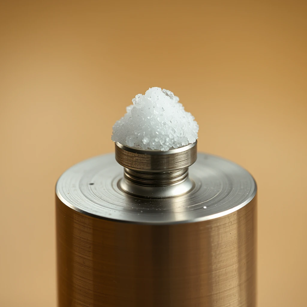
Salt buildup at HPLC connections is a frequent but often underestimated cause of flow restriction, pressure instability, leaks, and chromatographic performance loss. Precipitation and crystallization typically occur at wetted interfaces—fittings, unions, needle seats, mixers, check valves, and column inlet frits—where solvent composition, evaporation, and temperature gradients create localized conditions that favor salt deposition.
This guide provides a systematic, instrument-agnostic workflow to diagnose salt-related restrictions, safely recover affected components, and prevent recurrence through buffer selection, solvent handling, and proper connection practices.
Key principle: Salt solubility drops sharply in high organic content and at lower temperature. Even buffers that are fully soluble in water can crystallize at fittings when organic solvent evaporates or wicks away, leaving salts behind.
Typical Symptoms of Salt Buildup
Salt precipitation rarely causes immediate failure; instead, it produces progressive and misleading symptoms, including:
Gradual increase in system backpressure during a run, especially as organic content rises in gradients
Pressure spikes or instability coinciding with gradient steps
Intermittent pump cavitation alarms or poor priming behavior
White or translucent crystalline residue (“salt creep”) around fittings, column inlet, or autosampler needle seat
Reduced or irregular flow rate at a fixed pump setting (flow meter mismatch)
Peak broadening, loss of efficiency, retention time drift, or sensitivity loss due to partial blockage at the column inlet frit
Audible pump changes (check valve chatter, irregular strokes)
These symptoms often worsen over time and may temporarily improve after re-priming, masking the underlying cause.
Mechanism and Context: Why Salts Precipitate in HPLC Systems
Salt precipitation is driven by local solvent composition and micro-environment effects, not bulk reservoir chemistry:
High organic content (e.g., >50–60% acetonitrile or methanol) dramatically reduces the solubility of many inorganic salts.
Evaporation at exposed interfaces (threaded fittings, needle seats, waste ports) concentrates salts as volatile organics evaporate.
Temperature drops (cool lab air, column oven gradients, night shutdowns) further reduce solubility.
Dead volume and poor seating create stagnant zones where evaporation and concentration occur.
Phosphate buffers and high ionic strength solutions are particularly prone to precipitation during gradients with organic solvents.
Once crystals form, they narrow flow paths, damage seals, and create nucleation sites for further buildup.
High-Risk Locations for Salt Accumulation
Salt buildup is most common at points with flow disruption, evaporation, or pressure change:
Pump head and inlet/outlet check valves
Proportioning valve and low-volume mixers
Autosampler needle seat and rotor seal
Guard column and analytical column inlet frit
Inline filters and zero-dead-volume (ZDV) unions
Detector inlet tubing (rare, but must be protected during cleaning)
Rapid Diagnostic Workflow
Step 1: Establish a Pressure Baseline
Remove the column and install a short capillary or union to waste.
Set
flow = 0.5 mL/min,solvent = water.Pressure should be low and stable.
If pressure is elevated, the restriction is upstream (pump, mixer, autosampler, plumbing).
Step 2: Isolate by Segments
Sequentially bypass components:
Pump → mixer → degasser → autosampler → unions → detector.A sudden pressure drop when bypassing a segment identifies the restriction zone.
Step 3: Visual and Tactile Inspection
Inspect fittings for white crusts or damp residue.
Re-make suspect connections.
Remove the column and inspect the inlet frit and guard column.
Step 4: Buffer Compatibility Check
Confirm buffer identity, concentration, pH, and gradient range.
Phosphate buffers combined with high acetonitrile are a common cause.
Consider temperature effects—cool environments increase precipitation risk.
Step 5: Pump Prime and Check Valves
Prime each channel with water for 2–5 minutes via the purge line.
Erratic priming suggests fouled check valves; clean or replace.
Corrective Actions: Cleaning and Recovery
Controlled Aqueous Flush (System, No Column)
Flow = 0.2–0.5 mL/minSolvent = 100% waterDuration = 30–60 minutesFlush all channels gently to dissolve salts.
Avoid sudden high flow that could dislodge crystals downstream.
Organic-to-Aqueous Transition Protocol
If the system was at high organic:
Reduce organic to<20%before switching to water.
This staged approach prevents shock precipitation inside lines.
Targeted Component Cleaning
Autosampler needle seat
Remove and soak in water for 30 minutes; sonicate only if permitted; replace seals if worn.Unions and fittings
Disassemble; rinse and sonicate in water; replace deformed ferrules.Check valves
Backflush with water; replace if sealing is compromised.Inline filters
Replace 0.2 µm frits; do not attempt aggressive cleaning.
Column-Specific Remediation
If inlet frit is partially clogged:
Reverse-flush column with water at0.2–0.3 mL/minfor 30–60 minutes (if manufacturer allows).
Reinstall guard column or replace it—guards are sacrificial by design.
Re-make Connections Properly
Use ZDV fittings and square-cut capillaries.
Minimize exposed threads to reduce evaporation and salt creep.
Apply correct torque; avoid over-tightening polymer fittings.
Preventive Measures (Most Effective Long-Term Control)
Buffer Selection for Gradients
Prefer volatile buffers for gradient LC and LC–MS:
Ammonium acetate or ammonium formate (10–25 mM, pH 3–7).Avoid high-concentration phosphate buffers in steep organic gradients.
If phosphate is required, limit organic to ≤40–50% and control temperature.
Solvent Preparation and Handling
Prepare fresh buffers; filter through
0.2 µmmembranes.Keep reservoirs sealed; label ionic strength and pH clearly.
Avoid mixing incompatible buffers between channels.
End-of-Day Flushing Routine
100% water for 20–30 minutesFollow with
10–20% organic in water for 10–15 minutesStore columns per manufacturer guidance (often high organic, salt-free).
Sample Management
Desalt high-salt matrices (biological fluids, digests) via SPE or dilution.
Limit injected salt load.
Use guard columns and inline filters; replace based on pressure trends.
Environmental Controls
Maintain stable lab temperature.
Minimize airflow over fittings to reduce evaporation.
Use column ovens for consistent thermal conditions.
Decision Aids
Pressure rises only at high organic → precipitation upstream of column likely.
Pressure high without column → pump, mixer, autosampler, or plumbing restriction.
Pressure normalizes after replacing guard column → inlet frit clogging.
Unreliable priming with visible crystals → fouled check valves.
Technical Notes and Safety Considerations
Many inorganic salts (e.g., sodium phosphate) have very low solubility in acetonitrile.
A temperature drop of only 5–10 °C can precipitate marginally soluble salt mixtures.
PEEK is chemically resistant but susceptible to cold-flow if over-tightened.
Stainless steel tolerates most buffers but avoid prolonged exposure to high chloride at low pH.
Always divert flow to waste during aggressive flushing to protect detector flow cells.
Never exceed system pressure limits; increase flow gradually after cleaning.
Rule of thumb: Never switch directly from high-% organic to high-salt aqueous with the column installed—stage the transition and flush the system first.
Example Flush Protocol (System, No Column)
Flow = 0.2 mL/min; Solvent = 100% water; 30–60 minPrime each channel via purge line for 2–5 min
Increase to
0.5 mL/minfor 10–15 min if pressure is stableOptional:
10–20% organic for 10 minReconnect column; equilibrate at low organic before resuming method
Brief Summary
Salt buildup at HPLC connections is a leading cause of flow restriction, pressure instability, and chromatographic degradation, particularly in gradients with high organic content. Diagnose by isolating system segments, inspecting fittings for crystallization, and verifying buffer compatibility. Recover using controlled aqueous flushing and targeted cleaning of high-risk components. Prevent recurrence through volatile buffers, disciplined solvent handling, routine flushing, and proper connection practices.