Salt Crystallization at HPLC Pump Fittings and Flow Restriction
Practical guide to diagnose Salt Crystallization at HPLC Pump Fittings and Flow Restriction: symptoms, tests, and proven corrections to improve reproducibility.
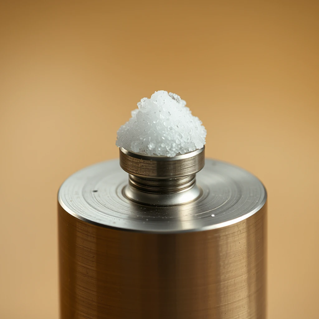
Salt Crystallization at HPLC Pump Fittings and Flow Restriction
Root Causes, Diagnostics, and Corrective Actions
Overview
Salt crystallization at HPLC pump fittings and upstream fluidic components is a frequent but often underestimated cause of flow instability, erratic pressure behavior, and chronic leaks. The problem most commonly arises in systems operating with aqueous buffered mobile phases, particularly non-volatile inorganic buffers such as phosphate, under high-organic conditions, during gradient mixing, or when seal-wash practices are inadequate.
As solvent evaporates at microleaks or local solvent composition changes exceed buffer solubility limits, salts precipitate and form crystalline deposits—often referred to as salt creep. These deposits accumulate around ferrules, pump heads, check valves, purge valves, inline filters, and low-pressure mixing components, progressively increasing flow resistance. The downstream effects include pressure spikes, retention time drift, peak distortion, baseline noise, and—in LC–MS workflows—accelerated source contamination.
This guide explains the physical and chemical mechanisms behind salt crystallization, provides a step-by-step diagnostic workflow, and outlines corrective and preventive strategies applicable to both isocratic and gradient HPLC methods.
Technical Background and Key Concepts
Understanding salt crystallization requires recognizing how buffer chemistry, solvent composition, and fluidic design interact under high pressure.
Buffer
A solution that stabilizes pH, typically composed of a weak acid or base and its conjugate salt (e.g., phosphate, acetate, formate).Volatile vs. non-volatile buffers
Volatile buffers (e.g., ammonium acetate or ammonium formate) evaporate readily and are preferred for LC–MS. Non-volatile buffers (e.g., phosphate) persist and readily form solid deposits.Solubility product (Ksp)
The thermodynamic limit governing how much of an ionic compound remains dissolved. Exceeding this limit results in precipitation.Ionic strength
Total concentration of ions in solution. High ionic strength can reduce solubility and increase viscosity.Gradient mixing
Changes in mobile-phase composition during a run. Rapid increases in organic solvent can sharply reduce salt solubility and cause local supersaturation.Check valves
One-way valves in the pump head that control solvent intake and delivery. Crystalline fouling disrupts sealing and priming.Ferrules
Compressible sealing elements that secure tubing inside fittings. Wear or deformation creates microleaks that seed crystallization.Inline filters and frits
Porous elements that trap particulates but can themselves become clogged with salt crystals.Seal wash
An auxiliary solvent flow around pump piston seals—typically water with 10–20% organic—to prevent salt deposition.Dead volume
Non-flowing or poorly swept volumes that promote stagnation and precipitation when solvent composition changes.
Typical Symptoms and Early Indicators
Salt crystallization rarely appears suddenly; it develops progressively and produces recognizable warning signs:
Pressure instability
Spikes, oscillations, or a gradual increase in backpressure at constant flow.Flow-rate irregularities
Difficult priming, under-delivery, or inconsistent pump stroke behavior.Visible residue
White, translucent, or granular deposits around fittings, pump heads, purge valves, or inlet lines.Chronic microleaks
Small leaks that leave dried buffer residue after evaporation.Baseline disturbances
Elevated noise or drift in UV/Vis detection; in LC–MS, salt shedding can degrade ionization efficiency.Retention variability
Shifts in retention time and peak broadening due to unstable flow or gradient composition errors.
Primary Root Causes
1. Microleaks and Evaporation at Fittings
Even microscopic leaks allow solvent to evaporate locally. As water evaporates preferentially, salts concentrate and crystallize at the leak interface, worsening sealing and accelerating restriction.
2. Buffer–Organic Incompatibility During Gradients
Inorganic buffers—especially phosphate above ~10–20 mM—have limited solubility in high percentages of acetonitrile or methanol. During gradients, local solvent composition can exceed the buffer’s solubility limit, triggering precipitation in mixing chambers, pump heads, and tubing.
3. Inadequate Seal Wash
Without continuous or refreshed seal wash, buffer dries on piston seals and adjacent passages, providing nucleation sites for crystals that propagate into the pump head.
4. High Buffer Concentration and Low Temperature
Lower temperatures reduce salt solubility. Concentrated buffers operated in cool laboratory environments crystallize more readily.
5. Stagnant Zones and Dead Volume
Poor mixing, oversized fittings, or unused channels create stagnant pockets where local supersaturation occurs during composition changes.
6. Fouled Inline Filters and Check Valves
Crystalline debris accumulates on frits and valve seats, increasing restriction and impairing valve sealing.
7. Improper Tubing and Ferrule Preparation
Oval cuts, burrs, misalignment, or incorrect torqueing create microleaks that initiate salt creep.
Diagnostic and Isolation Workflow
1. Decouple Column Backpressure
Remove the column.
Open the purge valve.
Set flow to ~1.0 mL/min with water.
Observe pressure; without a column, pressure should be minimal.
Persistently elevated pressure indicates upstream restriction.
2. Prime Solvent Channels Independently
Prime aqueous channel for 5–10 minutes.
Prime organic channel for 5–10 minutes.
Watch for cavitation, irregular strokes, or delayed solvent delivery—signs of check valve fouling.
3. Visual Inspection
Inspect fittings, pump head, purge valve, and inline components for white or translucent deposits. Wipe suspect areas; granular residue after drying strongly indicates crystallized salts.
4. Inline Filter and Frit Check
Temporarily remove or replace inline filters. A sudden pressure drop confirms filter fouling.
5. Check Valve Assessment
Erratic priming suggests inlet valve fouling; unstable delivery implicates outlet valves.
6. Leak Testing
Run water at low flow and observe fittings closely. Microleaks often become visible only under steady flow.
7. Composition Stress Test
Run short gradients without the column. Pressure increases at high organic strongly suggest upstream salt precipitation.
Corrective Actions
1. Dissolve and Flush Salt Deposits
Flush the system with water at moderate flow for extended periods (30–60 minutes for phosphate). Mild warming of the water can improve solubility.
2. Service Check Valves
Remove and sonicate check valves in water, rinse thoroughly, and reinstall with correct orientation.
3. Replace or Clean Inline Filters
Clogged frits should be replaced or thoroughly cleaned and flushed before reuse.
4. Repair Fittings and Ferrules
Recut tubing squarely, replace worn ferrules, and torque fittings correctly. Avoid reusing deformed ferrules.
5. Restore Seal Wash
Install or refresh a seal-wash solution (typically 80–90% water with 10–20% organic) to prevent future crystallization.
6. Re-prime and Recondition
Prime all channels, equilibrate with mixed solvent, and verify stable pressure both with and without the column.
7. Validate Gradient Behavior
Run a test gradient without the column to confirm pressure stability across the full composition range.
Preventive Measures and Best Practices
Buffer selection
Prefer volatile buffers for gradient methods and LC–MS. Limit phosphate concentration when high organic content is required.Buffer preparation
Adjust pH after full dissolution and filter all buffers to remove particulates.Seal-wash maintenance
Maintain an active seal wash and flush the system with water at the end of each day.System hygiene
Replace bottle inlet filters regularly and minimize dead volume.Environmental control
Avoid cold drafts or temperature gradients around the pump head.Mechanical discipline
Use appropriate ferrules and ensure proper tubing preparation and torqueing.Routine monitoring
Track baseline pressure without a column as an early indicator of developing restriction.
Impact on Chromatographic and Spectroscopic Performance
Salt crystallization disrupts flow accuracy and gradient fidelity, leading to poor reproducibility, peak distortion, and retention drift. In LC–MS, salt shedding severely compromises ionization efficiency and accelerates source fouling, increasing downtime and maintenance frequency.
Summary
Salt crystallization at HPLC pump fittings arises from microleaks, incompatible buffer–organic combinations, inadequate seal wash, and stagnant fluidic zones. The resulting deposits restrict flow, destabilize pressure, and degrade chromatographic performance. Systematic diagnosis—beginning with column removal and water flushing—combined with proper component servicing and buffer selection, resolves most cases. Preventive practices focused on buffer chemistry, seal-wash use, and mechanical integrity are essential for long-term system stability.